Concentrated microwave electrodeless ultravioletcatalysis waste gas treatment equipment

A kind of exhaust gas treatment equipment, the technology of infinite ultraviolet light, which is applied in the direction of gas treatment, chemical instruments and methods, and dispersed particle filtration, etc., can solve the problems of high cost of catalytic combustion equipment, difficult to meet the treatment effect, short residence time of exhaust gas, etc., and achieve structural Simple, reasonable design, and the effect of improving the processing effect

Pending Publication Date: 2018-08-28
陕西青朗万城环保科技有限公司
View PDF0 Cites 3 Cited by
  • Summary
  • Abstract
  • Description
  • Claims
  • Application Information

AI Technical Summary

Problems solved by technology

[0004] The purpose of the present invention is to overcome the deficiencies of the above-mentioned prior art, and provide a concentrated microwave non-polar ultraviolet photo-oxygen catalytic waste gas treatment equipment, mainly for harmless treatment of organic waste gas with large air volume and low concentration, and solve the cost of existing catalytic combustion equipment High, large equipment volume, high maintenance costs, and the existing photo-oxygen catalysis and plasma waste gas treatment methods are difficult to meet the standard due to the short residence time of waste gas

Method used


Image

  • Concentrated microwave electrodeless ultravioletcatalysis waste gas treatment equipment

Examples


specific Embodiment approach

[0023] It should be noted that the structures, proportions, sizes, etc. shown in the drawings attached to this specification are only used to match the content disclosed in the specification, for those who are familiar with this technology to understand and read, and are not used to limit the implementation of the present invention Any modification of the structure, change of the proportional relationship or adjustment of the size shall still fall within the scope of the technical content disclosed in the present invention without affecting the effect and purpose of the present invention. In the range.

[0024] At the same time, terms such as "upper", "lower", "left", "right", "middle" and "one" quoted in this specification are only for the convenience of description and are not used to limit this specification. The practicable scope of the invention and the change or adjustment of its relative relationship shall also be regarded as the practicable scope of the present inventi...

Embodiment 1

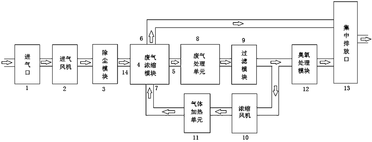
[0026] Such as figure 1 As shown, the present invention discloses a concentrated microwave stepless ultraviolet photo-oxygen catalytic exhaust gas treatment equipment, including an intake fan 2, a dust removal module 3, an exhaust gas concentration module 4, an exhaust gas treatment unit 8, a filter module 9, an ozone treatment module 12 and Concentrated discharge port 13, the output end of the air intake fan 2 is connected to the input end of the dust removal module 3, wherein the output end of the dust removal module 3 is connected to the input end of the waste gas concentration module 4, and the output ends of the waste gas concentration module 4 are respectively connected to the waste gas The input end of the processing unit 8 and the centralized discharge port 13, wherein the output end of the exhaust gas processing unit 8 is connected to the input end of the filter module 9, and the output end of the filter module 9 is connected to the input end of the ozone treatment mod...

Embodiment 2

[0036] Such as figure 1As shown, the present invention discloses a concentrated microwave stepless ultraviolet photo-oxygen catalytic waste gas treatment equipment, including an air inlet 1, an air intake fan 2, a dust removal module 3, a waste gas concentration module 4, a waste gas treatment unit 8, a filter module 9, Concentrating blower 10, gas heating unit 11, ozone treatment module 12 and centralized discharge port 13, the air inlet 1 is connected to the input end of the intake fan 2 through the air duct, wherein the output end of the intake fan 2 is connected to the dust removal module 3 The input end, wherein the output end of the dust removal module 3 is connected to the input end of the waste gas concentration module 4, and the output end of the waste gas concentration module 4 is respectively connected to the input end of the waste gas treatment unit 8 and the centralized discharge port 13, wherein the output of the waste gas treatment unit 8 terminal is connected t...


PUM


Abstract

The invention discloses concentrated microwave electrodeless ultravioletcatalysis waste gas treatment equipment. The equipment comprises an air inlet fan, a dedusting module, a waste gas concentrationmodule, a waste gas treatment unit, a filtering module, an ozone treatment module and a centralized exhaust opening, and the output end of the air inlet fan is connected with the input end of the dedusting module, wherein the output end of the dedusting module is connected with the input end of the waste gas concentration module; the output end of the waste gas concentration module is connected with the input end of the waste gas treatment unit and the centralized exhaust opening separately, wherein the output end of the waste gas treatment unit is connected with the input end of the filtering module; the output end of the filtering module is connected with the input end of the ozone treatment module, wherein the output end of the ozone treatment module is connected with the centralized exhaust opening. Waste gas is concentrated by 5-50 times through the waste gas concentration module, thus the amount of air entering the waste gas treatment unit is reduced, the waste gas staying timecan be prolonged by 5-50 times under the condition of not increasing the size of the waste gas treatment unit, and thus the treatment effect is improved by a large margin.

Description

technical field [0001] The invention belongs to a waste gas treatment system in the technical field of environmental protection, in particular to a concentrated microwave non-polar ultraviolet photo-oxygen catalytic waste gas treatment equipment. Background technique [0002] With the promulgation of environmental protection regulations, the requirements for the emission limits of VOC organic waste gas are becoming more and more stringent. VOC purification treatment projects with large air volume, low concentration and complex components are faced with the dilemma of large one-time investment and high operating costs. Although the traditional adsorption concentration + thermal oxidation or catalytic combustion combined VOC treatment process has a good treatment effect, generally exceeding 90%, the one-time investment of equipment is large and the operation and maintenance costs are high. [0003] In the traditional VOC organic waste gas treatment technology, although the cos...

Claims


Application Information

Patent Timeline
IPC IPC(8): B01D53/75B01D53/86B01D53/66B01D53/44B01D46/00B01D47/06
CPCB01D46/00B01D47/06B01D53/75B01D53/8675B01D53/8687B01D2253/102B01D2257/708B01D2259/806B01D2259/804B01D2259/40088
Inventor 马中发廉斌阮俞颖王欢
Owner 陕西青朗万城环保科技有限公司
Why Eureka
Try Eureka