Pressure-free guide type double-copper-foil cutting forming system

A copper foil cutting technology, which is applied in the field of non-pressing and extracting double copper foil cutting and forming system, can solve the problems of lower product yield, lead slip, copper foil surface wrinkles, etc., to improve precision and quality, Avoid slipping and wrinkling, and ensure the effect of cutting length

Pending Publication Date: 2018-08-28
KUNSHAN JUHONG MACHINERY TECH
View PDF0 Cites 3 Cited by
  • Summary
  • Abstract
  • Description
  • Claims
  • Application Information

AI Technical Summary

Problems solved by technology

[0003] At present, the thickness of copper foil commonly used in the PCB industry is 1 / 3OZ, 1 / 2OZ, 1OZ, (1OZ=35um) and there is a tendency to develop towards a thinner 1 / 4OZ. The higher the stability requirement, the thickness of 1 / 3OZ copper foil is only 12um. When extracting 1 / 3OZ, it will cause slippage or wrinkle on the surface of copper foil due to the problem of the wheel, which will reduce the product yield. If the industry subsequently uses 1 / 4OZ copper foil, this problem will be more serious, and it is urgent to develop a new extraction method to adapt to market development

Method used


Image

  • Pressure-free guide type double-copper-foil cutting forming system
  • Pressure-free guide type double-copper-foil cutting forming system
  • Pressure-free guide type double-copper-foil cutting forming system

Examples


Embodiment

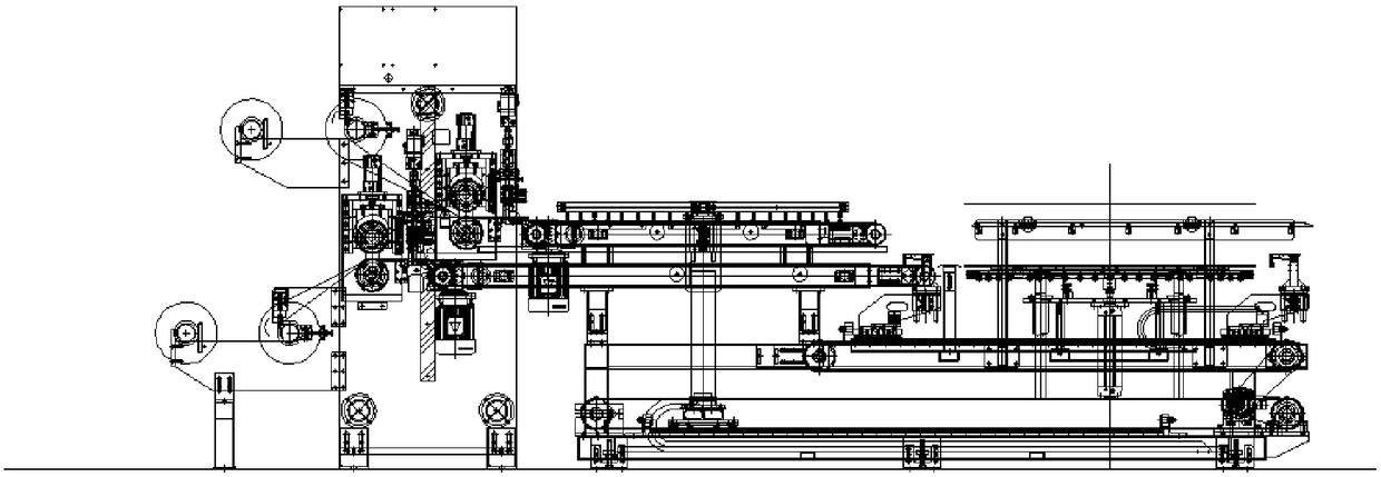
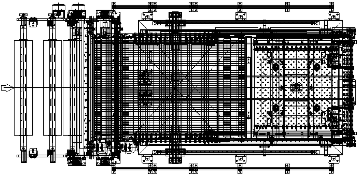
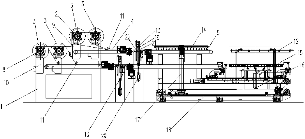
[0024] Embodiment: A non-pressing and extracting copper foil cutting and forming system, including a frame 1 and a copper foil cutting and conveying mechanism, at least one set of copper foil cutting and conveying mechanisms are arranged at intervals along the longitudinal direction on the frame 1, wherein The copper foil cutting and conveying mechanism includes a chuck 2, a sending drive device 9, a first plane conveying device 4, a first air pressure providing device, a cutting mechanism 13, a second plane conveying device 5 and a second air pressure providing device. The disk 2, the first plane conveying device 4, the cutting mechanism 13 and the second plane conveying device 5 are arranged sequentially along the copper foil conveying direction, and the chuck 2 is rotatably mounted on the frame 1, and the copper foil roll 3 can be coaxial Fixedly installed on the chuck 2, the sending drive device 9 drives the chuck 2 to rotate, and one end of the copper foil on the copper fo...


PUM


Abstract

The invention discloses a pressure-free guide type double-copper-foil cutting forming system. At least one copper foil cutting and conveying mechanism is arranged on a rack at intervals in the longitudinal direction. Each copper foil cutting and conveying mechanism comprises a chuck, a first plane conveying device, a cutting mechanism and a second plane conveying device are sequentially arranged in the conveying direction of copper foil. Conveying driving devices drive the chucks for mounting copper foil coils on the rack. The copper foil on the copper foil coils is led out to the surfaces ofthe corresponding first plane conveying devices. The first plane conveying devices and the second plane conveying devices can conduct conveying in the conveying direction of the copper foil correspondingly. First air pressure supply devices and second air pressure supply devices are used for providing air pressure making close contact with the surfaces of the first plane conveying devices and thesecond plane conveying devices for the copper foil on the surfaces of the first plane conveying devices and the second plane conveying devices. The first plane conveying devices, the cutting mechanisms and the second plane conveying devices are aligned and connected in pairs. The copper foil getting into the cutting areas of the cutting mechanisms can be cut off through the cutting mechanisms. Thepressure-free guide type double-copper-foil cutting forming system can convey the copper foil without being pressed by guide wheels, and the phenomenon that the copper foil slips and gets wrinkled inthe conveying process is avoided.

Description

technical field [0001] The invention relates to a cutting and stacking system, in particular to a non-pressing and drawing double copper foil cutting and forming system. Background technique [0002] In the stacking part of the circuit board production line, the first process is uncoiling and cutting of the copper foil roll, cutting the copper foil to the required size for sandwich forming, and then lifting it to the combination table by the crane for stacking. Before the copper foil is cut, the take-up wheel driven by the servo motor (the take-up wheel is one up and one down, one glue and one steel, and the copper foil is pressed by the pressure of the cylinder) rotates to drive the copper foil to move towards the cutting knife, and the servo motor The extraction length is converted according to the diameter of the extraction wheel, and thus the length is controlled. [0003] At present, the thickness of copper foil commonly used in the PCB industry is 1 / 3OZ, 1 / 2OZ, 1OZ, (...

Claims


Application Information

Patent Timeline
Patent Type & Authority Applications(China)
IPC IPC(8): B65H16/10B65H23/34B65H35/06B65H20/10B65H29/16B65H19/12B65H29/24B26F1/40B26D7/22
CPCB65H16/10B26D7/22B26F1/40B65H19/126B65H20/10B65H23/34B65H29/16B65H29/241B65H35/06B65H2701/1133B65H2701/173
Inventor 施元中
Owner KUNSHAN JUHONG MACHINERY TECH
Why Eureka
Try Eureka