
Self-locating method and system of operation robot under multi-suspended-pipeline scene

An operating robot and autonomous positioning technology, which is applied in the directions of instruments, measuring devices, surveying and navigation, etc., can solve the problems of poor positioning accuracy, easy wear and tear of two-dimensional codes, complex laying, etc., and achieve the effect of reducing errors

Active Publication Date: 2018-08-28
SOUTHWEAT UNIV OF SCI & TECH
View PDF4 Cites 4 Cited by
  • Summary
  • Abstract
  • Description
  • Claims
  • Application Information

AI Technical Summary

Problems solved by technology

In response to this task requirement, the existing methods usually adopt two technical solutions: one is to place a QR code directly under the pipeline, and use the camera on the robot to scan the QR code one by one to complete the scene positioning and navigation of the robot. This method has a two-dimensional The code is easy to wear, and the positioning accuracy is slightly poor due to the relatively wide two-dimensional code itself; the second is to place RFID radio frequency identification tags in the scene, and the robot completes scene positioning and autonomous navigation through the strength and phase of the received radio frequency signal. However, this method also has many problems such as being susceptible to electromagnetic interference, complex laying, and poor positioning accuracy.

Method used

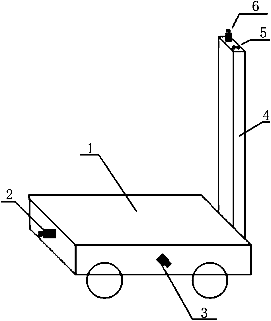

Image

  • Self-locating method and system of operation robot under multi-suspended-pipeline scene
  • Self-locating method and system of operation robot under multi-suspended-pipeline scene
  • Self-locating method and system of operation robot under multi-suspended-pipeline scene

Examples


Embodiment Construction

[0044] The specific embodiments of the present invention are described below so that those skilled in the art can understand the present invention, but it should be clear that the present invention is not limited to the scope of the specific embodiments. For those of ordinary skill in the art, as long as various changes Within the spirit and scope of the present invention defined and determined by the appended claims, these changes are obvious, and all inventions and creations using the concept of the present invention are included in the protection list.

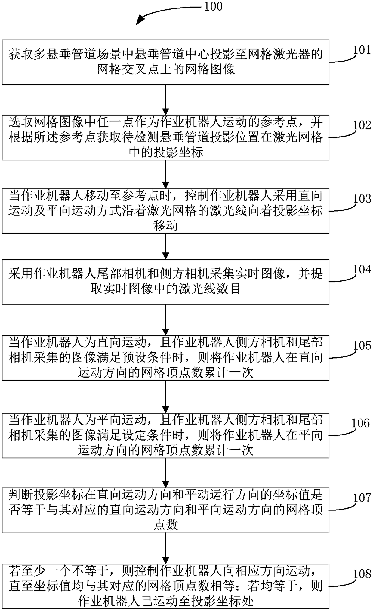
[0045] refer to figure 1 , figure 1 It shows the flow chart of the autonomous positioning method of the working robot in the scene of multiple overhanging pipelines; figure 1 As shown, the method 100 includes step 101 to step 108 .

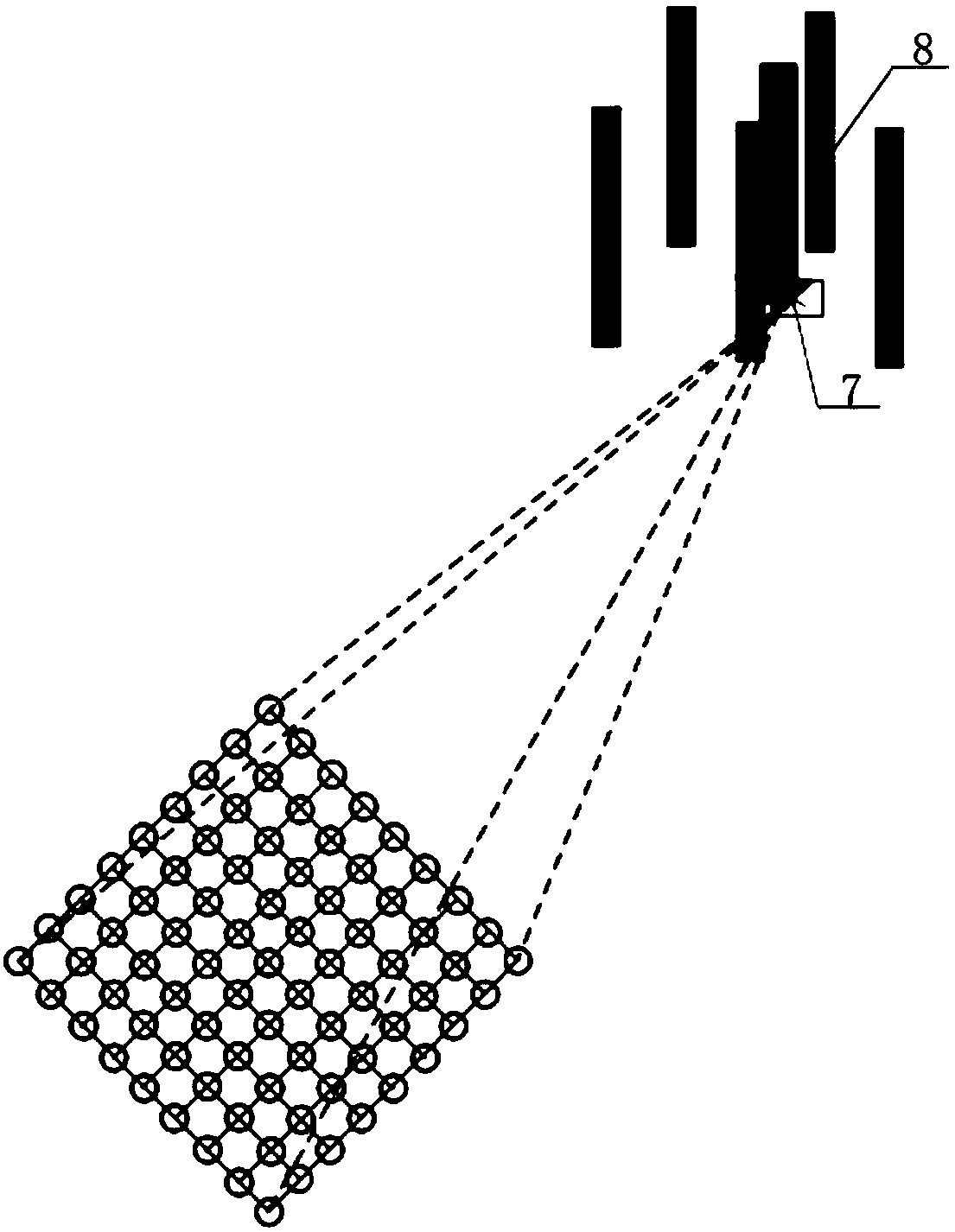
[0046] In step 101 , the grid image of the projection of the center of the suspension pipeline 8 onto the grid intersection of the grid laser 7 in the scene with multiple suspension pipelines...


PUM


Abstract

The invention discloses a self-locating method and system of an operation robot under a multi-suspended-pipeline scene. The locating method comprises the steps of obtaining a grid image and projectioncoordinates of suspended pipelines to be operated in the grid image; controlling the operation robot to move towards the projection coordinates along laser lines of laser grids by adopting straight direction motion and horizontal direction motion; adopting a tail camera and a side camera of the operation robot for collecting a real-time image, and extracting the number of laser lines in the real-time image; when the operation robot performs straight direction motion or the horizontal direction motion, and the images collected by the side camera and the tail camera meet preset conditions or set conditions, adding one for the vertex number of the grids of the operation robot in the straight direction motion or the horizontal direction motion; judging whether the projection coordinates are equal to the vertex number of the grids in the corresponding straight direction motion direction and the horizontal direction motion direction; if at least one coordinate is not equal to the vertex number, controlling the operation robot to move in the corresponding direction till all the coordinates are equal to the vertex number; if the coordinates are equal to the vertex number, indicating thatthe operation robot has moved to the projection coordinates.

Description

technical field [0001] The invention relates to the fields of computer vision and robot automatic control, in particular to an autonomous positioning method and a positioning system for an operating robot in a scene of multiple overhanging pipelines. Background technique [0002] In recent years, with the development of intelligence and automation, mobile intelligent robots have played an increasingly important role in the fields of manufacturing, logistics and transportation, and industrial inspection. The research on automatic positioning technology of mobile robots has also become the current robot research field. According to different application scenarios, the existing autonomous positioning and navigation of robots mainly creates or obtains feature information for map building and navigation in the scene through two-dimensional code marks, magnetic strip guide rails, lasers, cameras, etc. And according to this characteristic information, it is determined that the robo...

Claims


Application Information

Patent Timeline
Patent Type & Authority Applications(China)
IPC IPC(8): G01C21/00
CPCG01C21/00
Inventor 刘桂华邓鑫徐锋张华邓豪龙惠民
Owner SOUTHWEAT UNIV OF SCI & TECH
Learn More