
A realization method of spwm pulse signal based on mcu

An implementation method and technology of pulse signal, which is applied to industrial fast control to provide SPWM digital pulse. The MCU-based SPWM pulse signal implementation field can solve the problems of difficult debugging, unoptimized algorithm, low precision, etc., so as to improve the operation efficiency. and real-time control capabilities, improve real-time control capabilities, and speed up the effect of computing speed

Active Publication Date: 2020-12-08
ZHEJIANG UNIV
View PDF5 Cites 0 Cited by
  • Summary
  • Abstract
  • Description
  • Claims
  • Application Information

AI Technical Summary

Problems solved by technology

[0004] However, when the analog circuit of the operational amplifier or the digital-analog hybrid circuit is used to generate the SPWM waveform, due to the low precision of the components themselves, the generated SPWM waveform will be distorted and the precision is not high.
However, using a computer or a single-chip microcomputer to realize SPWM control is limited by the main frequency of the system, processor resources, and memory resources. When the control parameters need to be changed, the speed of recalculating the SPWM waveform is limited, and the accuracy is poor due to the limitation of the operation speed; Logic circuits are difficult to debug, which will cause a lot of waste of manpower and economic costs
[0005] In general, the current SPWM waveform generation technology either uses an operational amplifier analog circuit or a digital-analog hybrid circuit, resulting in poor waveform quality and low precision; or uses a computer or a single-chip microcomputer to realize SPWM control, and the algorithm has not been optimized. , the speed of recalculating and generating SPWM waveform after the parameter is changed is limited, and the accuracy is poor due to the limitation of the operation speed; or it needs to use a special logic circuit, which is difficult to debug and will cause a lot of waste of manpower and economic costs

Method used


Image

  • A realization method of spwm pulse signal based on mcu
  • A realization method of spwm pulse signal based on mcu
  • A realization method of spwm pulse signal based on mcu

Examples


Embodiment Construction

[0031] In order to facilitate the understanding and implementation of this invention by those of ordinary skill in the art, the present invention will be further described in detail below in conjunction with the accompanying drawings and embodiments. It should be understood that the implementation examples described here are only used to illustrate and explain the present invention, and are not intended to limit this invention.

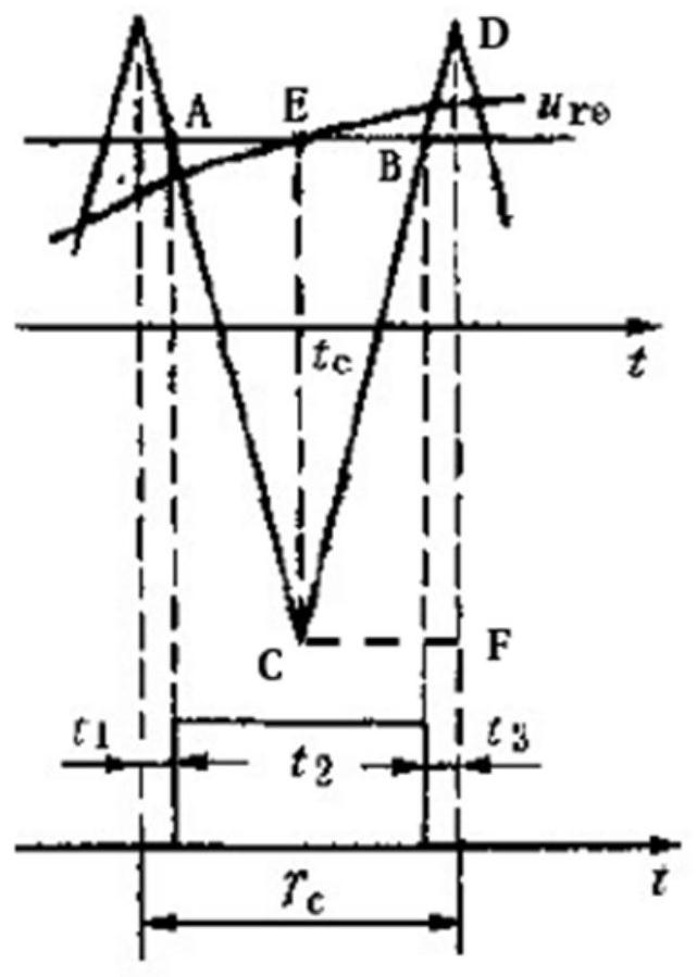
[0032] The invention adopts a symmetrical regular sampling method, adopts an optimized SPWM waveform generation algorithm in the program writing process, and uses MCU software to simulate multithreading in actual embedded development to generate the SPWM waveform.

[0033] The invention adopts the symmetrical rule sampling method, determines the mathematical basis of SPWM wave calculation, and reduces the calculation amount on the mathematical level.

[0034] The optimized SPWM waveform generation algorithm adopted in the present invention, according ...


PUM


Abstract

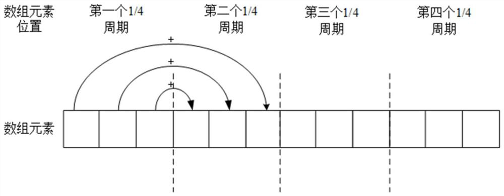
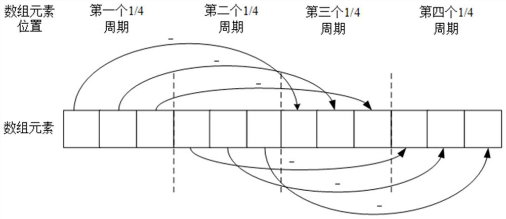
The invention discloses an MCU (Microprogrammed Control Unit)-based SPWM (Sinusoidal Pulse Width Modulation) pulse signal implementation method. The method comprises the steps of firstly, determininga generation mode of an SPWM wave by use of a symmetric regular sampling method; then, calculating an item which is not changed and contains a sine function in a subsequent actual control, and storingthe item into an array; calculating comparison time of the SPWM wave at the period of one quarter sine wave of a phase A according to a calculation formula of a duty ratio of a SPWM waveform, and storing the comparison time into the first one quarter part of a comparison time array of the SPWM wave of the phase A; obtaining the comparison time of latter three quarters parts of the phase A according to symmetry of a sine wave, then obtaining the comparison time array of the SPWM wave of a phase B and the comparison time array of the SPWM wave of a phase C according to characteristics of phasedifference of a three-phase SPWM wave, and finally obtaining a square wave of the duty ratio changed according to a sine law through interception of a triangular wave. With the method, the operation amount in an SPWM waveform process can be reduced, the calculation process is accelerated, the consumption of a processor and a memory resource is reduced and the precision for generation of the SPWM waveform is improved under the same condition.

Description

technical field [0001] The invention belongs to the technical field of control or regulation of electromechanical converters, and in particular relates to a method for realizing an MCU-based SPWM pulse signal, in particular providing SPWM digital pulses for industrial fast control. Background technique [0002] The sinusoidal pulse width modulation (Sinusoidal Pulse Width Modulation, SPWM) method is a relatively mature and widely used PWM method at present. This method is to make a natural or regular width modulation of multiple pulses in each sine cycle, so that it can sequentially modulate the phase angle and area equivalent to the value of the sine function, which is equivalent to the pulse sequence of the sine wave, forming a constant amplitude Sinusoidal current output with unequal width. [0003] At present, there are many ways to generate SPWM waveforms. You can use operational amplifiers to form SPWM analog circuits; you can also use digital circuits or analog-digit...

Claims


Application Information

Patent Timeline
Patent Type & Authority Patents(China)
IPC IPC(8): G06F1/025H02M1/08
CPCG06F1/025H02M1/082
Inventor 唐滢淇董树锋
Owner ZHEJIANG UNIV
Learn More