
Flow plating device for copper tube of crystallizer

A crystallizer copper tube, vertical technology, applied in the electrolysis process, electrolysis components and other directions, can solve the problems of high labor intensity, low production efficiency, unstable product quality, etc., to reduce labor intensity, improve production efficiency, and improve mechanization. Production level effects

Inactive Publication Date: 2018-08-31
QINHUANGDAO SHOUGANG CHANGBAI MOLD
View PDF2 Cites 1 Cited by
  • Summary
  • Abstract
  • Description
  • Claims
  • Application Information

AI Technical Summary

Problems solved by technology

At present, the fluid electroplating method is more and more used for the electroplating of mold copper tubes. However, the clamping and fixing of mold copper tubes on the electroplating station and the clamping of conductive devices have always been done manually, which is labor-intensive. Low production efficiency and unstable product quality

Method used


Image

  • Flow plating device for copper tube of crystallizer
  • Flow plating device for copper tube of crystallizer
  • Flow plating device for copper tube of crystallizer

Examples


Embodiment Construction

[0012] The specific embodiment of the present invention will be described with reference to the accompanying drawings.

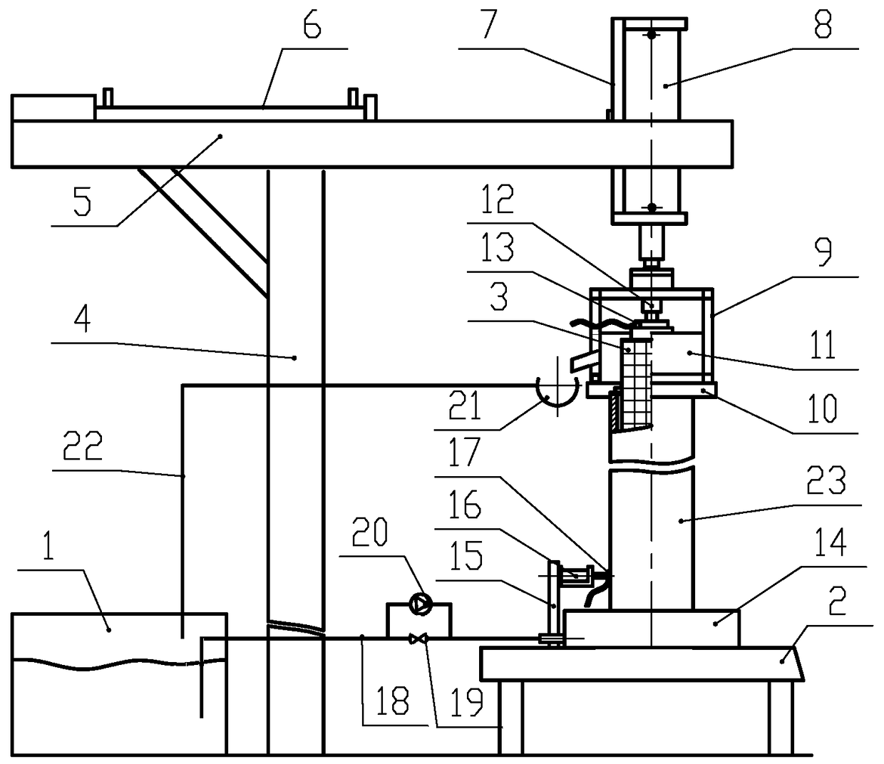
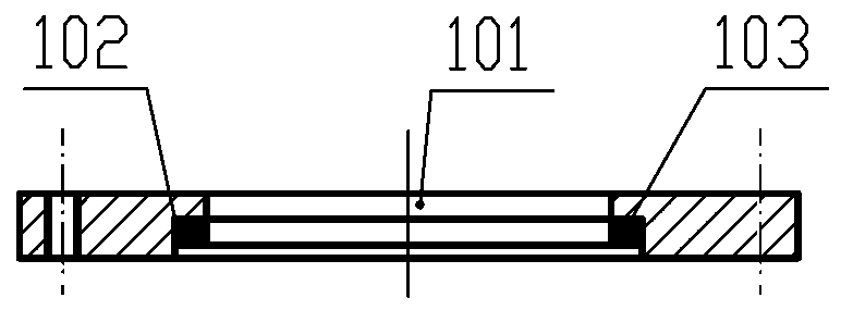
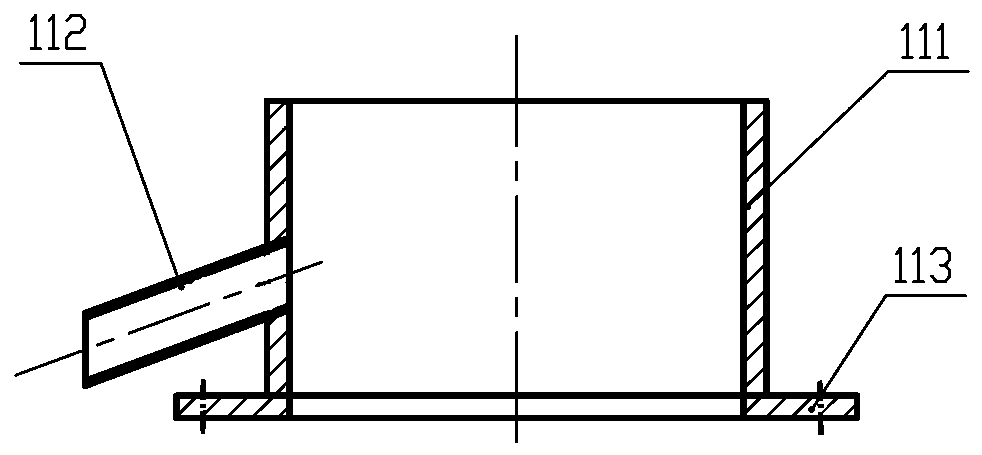
[0013] like figure 1 , the crystallizer copper tube flow plating device, comprising a liquid storage tank 1, a workbench 2 and a cylindrical nickel anode 3, a vertical support 4 is provided on one side of the workbench 2, and the upper end of the support 4 is provided with Beam guide 5, such as figure 1 In an embodiment, the beam guide rail 5 adopts a cantilever structure. A horizontal cylinder 6 and a sliding seat 7 cooperating with the crossbeam guide 5 are arranged on the crossbeam guide 5, the horizontal cylinder 6 is fixed on the outer upper part of the crossbeam guide 5, and the front end of the piston rod of the horizontal cylinder 6 Connected with the sliding seat 7, the horizontal cylinder 6 is used to drive the sliding seat 7 to move horizontally on the beam guide rail 5. The sliding seat 7 is provided with a vertical cylinder 8, the lower end o...


PUM


Abstract

The invention relates to a flow plating device for a copper tube of a crystallizer. The flow plating device is provided with a bracket provided with horizontal and vertical air cylinders, wherein thehorizontal air cylinder is connected to the vertical air cylinder through a sliding seat; an upper fixing clamping mold plate, the lower end of the vertical air cylinder is connected to an upper moldplate fixing frame, an overflow cap and an anode connecting air cylinder are assembled on the frame, a lower fixed mold plate and a cathode connecting air cylinder are arranged on a worktable, a to-be-plated copper tube and a barrel-shaped nickel anode are vertically arranged on the lower fixed mold plate and is clamped and fixed through the upper fixing and clamping mold plate, a plating solutionin a liquid storage tank enters the to-be-plated copper tube through a transfusion pump and the lower fixed mold plate and flows back to the liquid storage tank through an upper liquid return pipe, aplating solution in the to-be-plated copper tube flows back to the liquid storage tank through an electromagnetic valve and a lower liquid entering and returning pipe connected to the transfusion pump in parallel, and a power supply is turned on of cut off through an anode connecting air cylinder and a cathode connecting air cylinder. The flow plating device improves the mechanical production level of the copper tube of the crystallizer in the plating process, so that the labor intensity of workers can be alleviated effectively, the production efficiency is improved, and the quality of compound plating of an inner hole of the copper tube of the crystallizer is ensured.

Description

technical field [0001] The invention relates to crystallizer copper tube production equipment, in particular to a crystallizer copper tube flow plating device. Background technique [0002] Fluid plating is referred to as flow plating. Compared with traditional tank immersion plating, it has strong interchangeability, sufficient ion exchange, fast plating speed, short plating time, uniform and dense coating, and can save a lot of tank matching costs and other accessories. Cost and other advantages, has been widely used in the field of electroplating. At present, the fluid electroplating method is more and more used in the electroplating of mold copper tubes. However, the clamping and fixing of mold copper tubes on the electroplating station and the clamping of conductive devices have always been done manually, which is labor-intensive. The production efficiency is low and the product quality is unstable. Contents of the invention [0003] The purpose of the present inven...

Claims


Application Information

Patent Timeline
Patent Type & Authority Applications(China)
IPC IPC(8): C25D7/04C25D5/08C25D17/00
CPCC25D5/08C25D7/04C25D17/00
Inventor 赵宗华李鹏王洪林
Owner QINHUANGDAO SHOUGANG CHANGBAI MOLD
Learn More