Compression resistance and tensile force integral testing device and method thereof for electromagnet

A test device, electromagnet technology, applied in the direction of measuring device, using stable tension/pressure test material strength, instruments, etc., can solve the problems of inaccurate sensor measurement data, cumbersome operation process, affecting service life, etc., to achieve convenience Subsequent tests, convenient operation, and extended service life

Active Publication Date: 2018-08-31
KENDRION ELECTROMAGNETIC TECH SUZHOU
View PDF8 Cites 3 Cited by
  • Summary
  • Abstract
  • Description
  • Claims
  • Application Information

AI Technical Summary

Problems solved by technology

[0004] However, in the above invention, the cylinder is directly connected to the sensor, and the force is relatively large at the moment of work and the moment of completion of the work, resulting in inaccurate measurement data of the sensor and easy damage to the sensor.
In addition, whether there is a problem with the coil in the electromagnet cannot be detected directly. It needs to be detected by other detection coil detection devices. The operation process is cumbersome and affects work efficiency.
In particular, the outer surface of the electromagnet needs to have a certain pressure resistance. If there is no certain pressure resistance, it is very easy to be pierced by external protrusions or sharp objects, which will not only affect the service life, but may even damage the body. Accidents such as leakage, circuit breaker, etc.

Method used


Image

  • Compression resistance and tensile force integral testing device and method thereof for electromagnet
  • Compression resistance and tensile force integral testing device and method thereof for electromagnet

Examples


Embodiment Construction

[0030] The present invention will be described in detail below in conjunction with specific embodiments shown in the accompanying drawings. However, these embodiments are not limited to the present invention, and structural, method, or functional changes made by those skilled in the art according to these embodiments are included within the protection scope of the present invention.

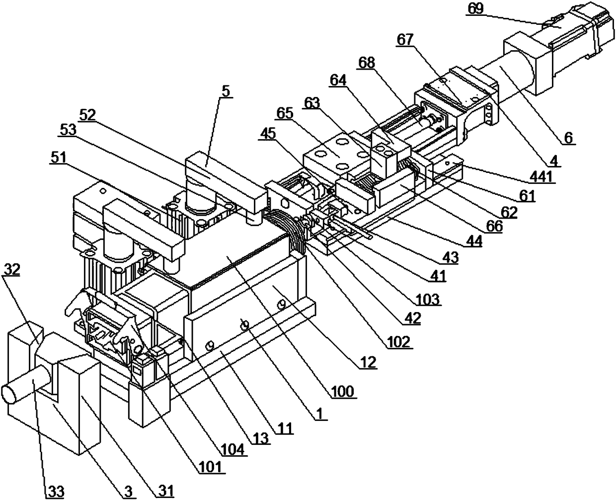
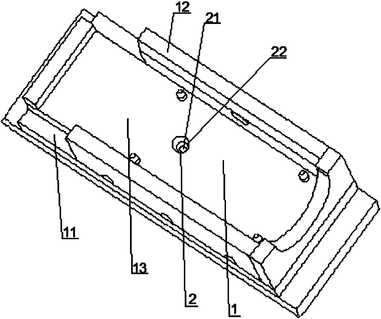
[0031] Such as Figure 1 to Figure 2 As shown, the present invention discloses an electromagnet compression and tension integrated testing device, the electromagnet at least includes a body 100, one end of the body 100 is provided with a connector 101 electrically connected to its internal coil, and the other end is provided with a A connecting head 102 that can move horizontally relative to it, and a bolt 103 is fixed on the connecting head 102 . Wherein, the body 100 is provided with a coil (not shown in the figure), and the piston (not shown in the figure) inside the coil will generate magnet...


PUM


Abstract

The invention discloses a compression resistance and tensile force integral testing device and method thereof for an electromagnet. The electromagnet comprises an electromagnet body, one end of the electromagnet body is provided with a connector electrically connected with a coil inside the electromagnet body, the other end of the electromagnet body is provided with a connecting head capable of horizontally moving relative to the electromagnet body, and a bolt is fixedly arranged on the connecting head; the device comprises a supporting plate and a bearing platform used for bearing the electromagnet and fixedly arranged on the supporting plate, and a compression resistance assembly used for testing the compression resistance property of the electromagnet is arranged on the bearing platform; a power-on assembly and a force servo assembly are further arranged on two ends of the bearing platform, and the power-on assembly is located at one end of the connector and can be electrically connected with the connector; the force servo assembly is located at one end of the connecting head and can drive the connecting head to move in the axle wire direction of the electromagnet. The device and method have the advantages that the structure is simple, the design is elaborate, detection for magnetism and compression resistance of electromagnetic wires is achieved, the testing accuracy is improved, and the service life of a pressure sensor is prolonged.

Description

technical field [0001] The invention relates to an electromagnet testing device, in particular to an electromagnet anti-compression and tension integrated testing device and method thereof. Background technique [0002] In recent years, with the rapid development of the automobile industry, aviation industry, and shipbuilding industry, the demand for the number of electromagnets has gradually increased, and the requirements for performance indicators such as speed and electromagnetic force have become higher and higher. The degree of development will directly affect our country's competitive market position in the world's military, aviation, automobile and other high-tech fields and the rapid development of our national economy, which requires us to design and manufacture a fast, accurate and efficient electromagnet performance testing system. [0003] As disclosed in the authorized announcement number 203024917U, an electromagnet tensile test device includes a support plate...

Claims


Application Information

Patent Timeline
Patent Type & Authority Applications(China)
IPC IPC(8): G01N3/02G01N3/08
CPCG01N3/02G01N3/08
Inventor 郭超田传宝吕友权
Owner KENDRION ELECTROMAGNETIC TECH SUZHOU
Why Eureka
Try Eureka