
Lock detection circuit for phase-locked loop

A lock detection, phase-locked loop technology, applied in electrical components, automatic power control, electrical digital data processing and other directions, can solve the problems of lock detection signal jumping, misjudgment, etc. Flexible effect

Inactive Publication Date: 2018-08-31
SHANGHAI INST OF MICROSYSTEM & INFORMATION TECH CHINESE ACAD OF SCI
View PDF10 Cites 6 Cited by
  • Summary
  • Abstract
  • Description
  • Claims
  • Application Information

AI Technical Summary

Problems solved by technology

[0006] However, when the lock detection circuit is bombarded by a single event, the lock detection signal may jump, that is, the lock detection signal is affected by the single event effect and outputs an out-of-lock signal, thereby causing misjudgment

Method used


Image

  • Lock detection circuit for phase-locked loop
  • Lock detection circuit for phase-locked loop
  • Lock detection circuit for phase-locked loop

Examples


Embodiment Construction

[0052] Below in conjunction with the drawings, preferred embodiments of the present invention are given and described in detail.

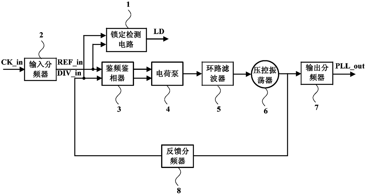
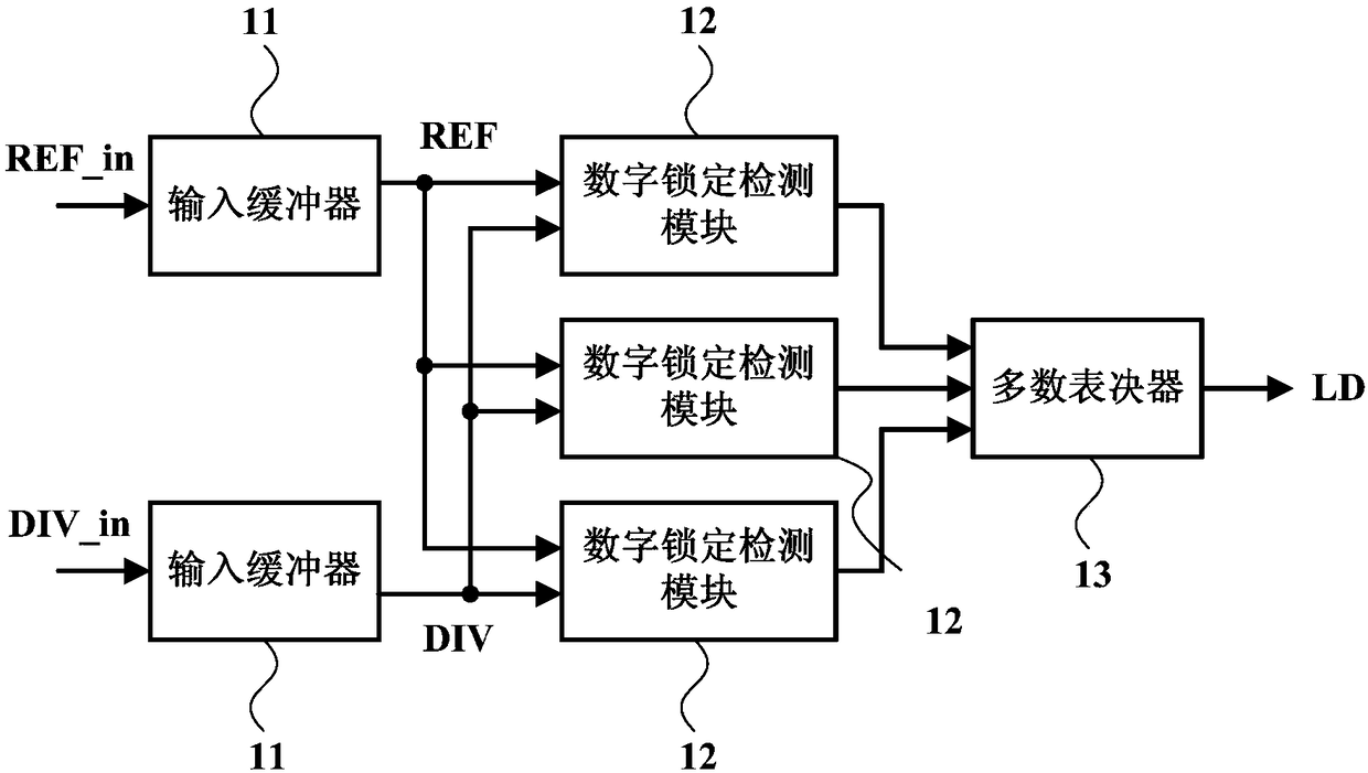
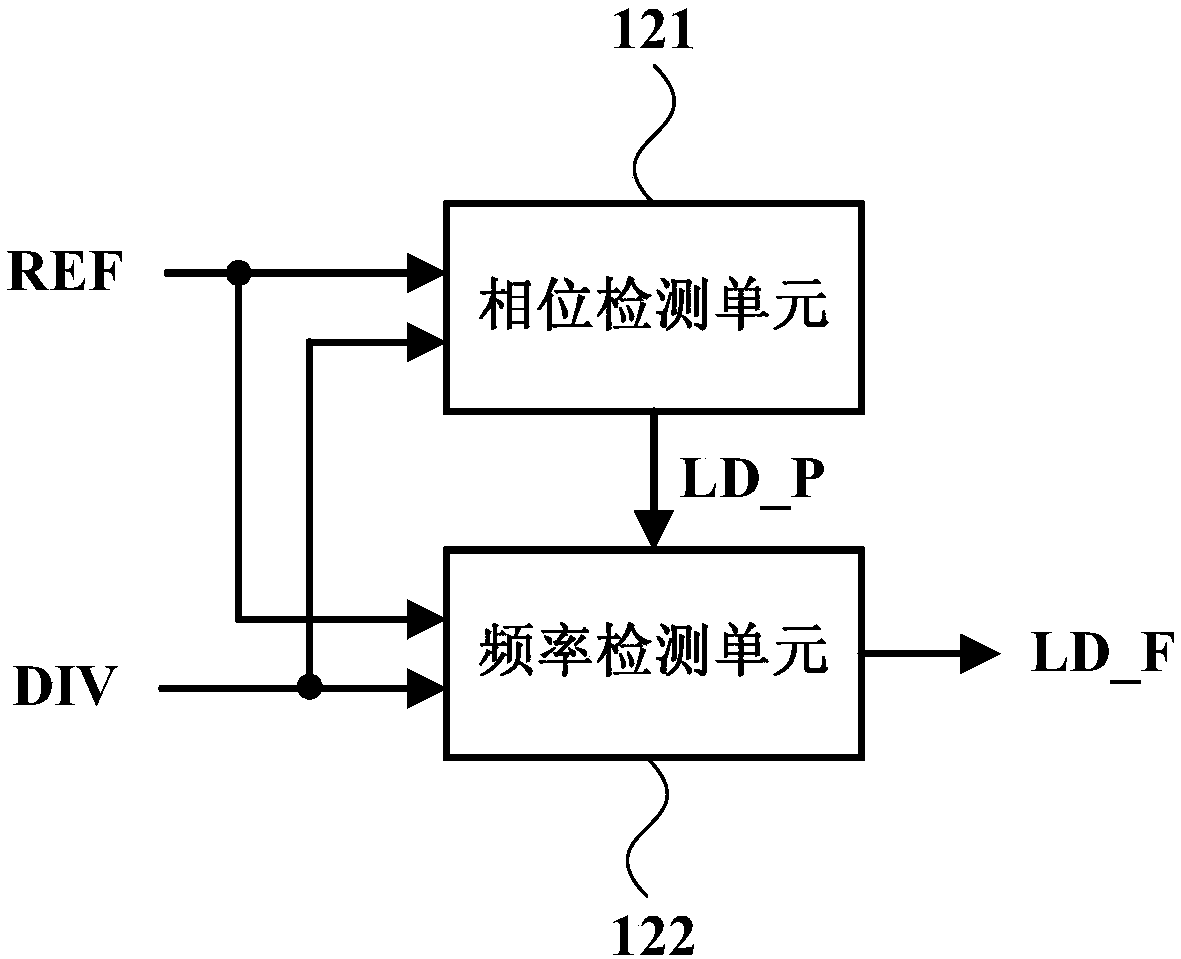
[0053] Such as figure 1 , 2 As shown, the present invention is a lock detection circuit 1 for a phase-locked loop, which includes: two input buffers 11, three redundant, digital lock detection modules 12 with the same structure and a majority voter 13 , wherein, one input buffer 11 receives the reference signal REF_in (the reference signal REF_in is obtained according to the input signal CK_in through the input frequency divider 2 of the phase-locked loop), and simultaneously provides the reference buffer signal REF to the three digital lock detection modules 12; Another input buffer 11 receives the feedback signal DIV_in (the feedback signal DIV_in is obtained according to the output signal of the voltage-controlled oscillator 6 through the feedback frequency divider 8 of the phase-locked loop), and provides feedback buffering to the three digita...


PUM


Abstract

The invention relates to a lock detection circuit for a phase-locked loop. The phase-locked loop comprises an input frequency divider and a feedback frequency divider, and the lock detection circuit comprises two input buffers, three digital lock detection modules and a majority voter, wherein one of the input buffers receives a reference signal provided by the input frequency divider and simultaneously provides reference buffer signals to the three digital lock detection modules; the other input buffer receives a feedback signal provided by the feedback frequency divider and simultaneously provides feedback buffer signals to the three digital lock detection modules; each of the digital lock detection modules compares the reference buffer signals with the feedback buffer signals; and the majority voter generates a lock detection signal based on output signals of the three digital lock detection modules. The scheme of the invention has the advantages of strong flexibility, anti-single event effect and the like.

Description

technical field [0001] The invention relates to a highly reliable integrated circuit, in particular to a lock detection circuit for a phase-locked loop. Background technique [0002] The phase-locked loop circuit is an automatic phase control system, which makes the oscillator output signal track the reference input signal through a phase negative feedback loop to obtain a low-jitter output signal. In 1932, Bellescize realized the phase-locked loop for the first time by using vacuum electron tubes. Due to the cost and technical complexity, the phase-locked loop was mainly used in the field of space technology in the early days, such as: missile beacon tracking, satellite communication, etc. It was not until the integration of phase-locked loops that they were widely used in electronic and communication systems. Today, phase-locked loops are known as the "heart" of electronic systems, and are widely used in various clock systems, including frequency synthesizers, clock data ...

Claims


Application Information

Patent Timeline
IPC IPC(8): H03L7/26G06F17/50
CPCG06F30/367H03L7/26
Inventor 陈卓俊董业民单毅
Owner SHANGHAI INST OF MICROSYSTEM & INFORMATION TECH CHINESE ACAD OF SCI
Learn More