Abrasives

A technology of abrasive grains and abrasive layers, used in abrasives, metal processing equipment, electrical components, etc., can solve the problem of high grinding cost and achieve the effect of low grinding cost

Active Publication Date: 2020-06-05
BANDO CHEM IND LTD
View PDF12 Cites 0 Cited by
  • Summary
  • Abstract
  • Description
  • Claims
  • Application Information

AI Technical Summary

Problems solved by technology

However, the existing free abrasive grain grinding and semi-fixed abrasive grain grinding must continuously supply the abrasive grains to the grinding material, and the grinding cost is high.

Method used


Image

  • Abrasives
  • Abrasives
  • Abrasives

Examples


no. 1 Embodiment

[0047] Hereinafter, a first embodiment of the present invention will be described in detail with appropriate reference to the drawings.

[0048]

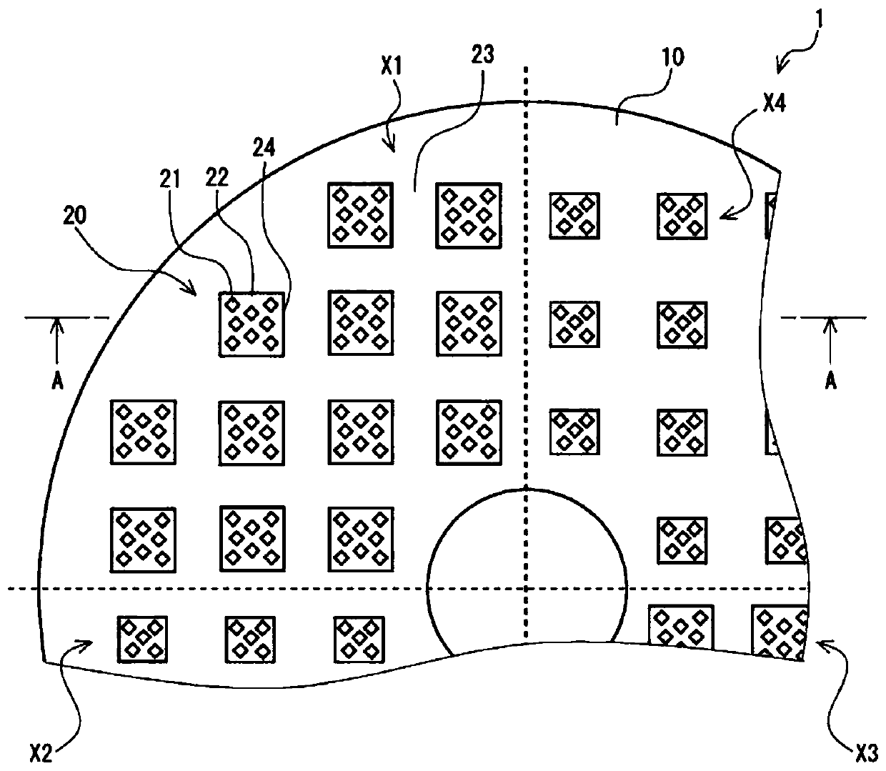
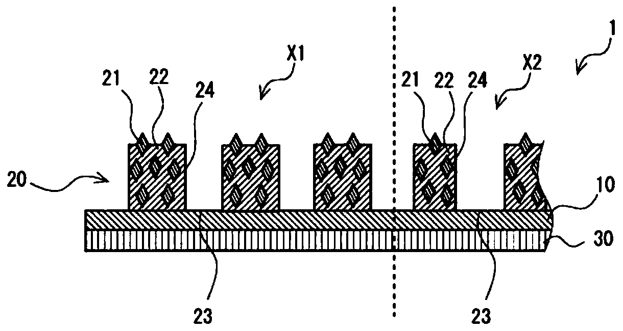
[0049] Figure 1A and Figure 1B The abrasive material 1 shown is disc-shaped and mainly includes a base material 10 and an abrasive layer 20 laminated on the surface side of the base material 10 . In addition, the abrasive material 1 includes an adhesive layer 30 laminated on the back side of the base material 10 . The grinding material 1 is disposed on a grinding platen of a known grinding device, and is ground by the grinding device while rotating while contacting the object to be ground. That is, the grinding direction of the grinding material 1 is the circumferential direction of the substrate 10 .

[0050] (Substrate)

[0051] The base material 10 is a plate-shaped member for supporting the polishing layer 20 .

[0052]The material of the substrate 10 is not particularly limited, and examples include: polyethylene tereph...

no. 2 Embodiment

[0108] Hereinafter, a second embodiment of the present invention will be described in detail with appropriate reference to the drawings.

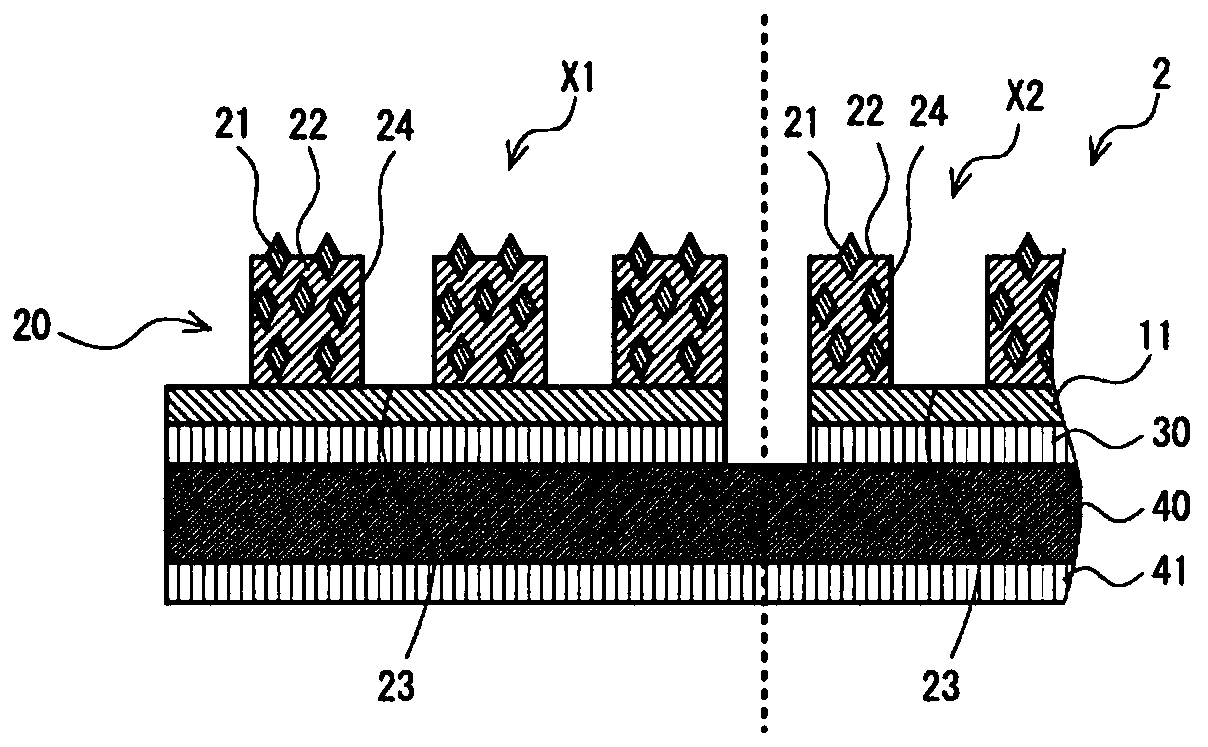
[0109] figure 2 The abrasive material 2 shown is disk-shaped, and mainly includes a base material 11 and an abrasive layer 20 laminated on the surface side of the base material 11 . In addition, the abrasive material 2 includes an adhesive layer 30 laminated on the back side of the base material 11 . Furthermore, the abrasive material 2 includes a support 40 laminated via an adhesive layer 30 and a support adhesive layer 41 laminated on the back side of the support 40 . In addition, the same code|symbol is attached|subjected about the same component as 1st Example, and description is abbreviate|omitted.

[0110] (Substrate)

[0111] The substrate 11 is a plate-shaped member for supporting the polishing layer 20 . The substrate 11 is divided into a first region X1, a second region X2, a third region X3, and a fourth region X4 along the ...

Embodiment 1

[0148] Diamond abrasive grains were prepared, and the average particle diameter was measured using "Microtrac MT3300EXII" manufactured by Nikkiso Co., Ltd. The average particle size of the diamond abrasive grains is 44 μm. Furthermore, the type of diamond in the abrasive grains is treated diamond coated with 55% by mass nickel.

[0149] Sodium silicate (No. 3 sodium silicate) as binder, the diamond abrasive grains, and alumina (Al 2 o 3 , with an average particle size of 12 μm) were mixed and prepared so that the content of the diamond abrasive grains relative to the abrasive layer became 5 vol % and the content of the filler relative to the abrasive layer became 71 vol % to obtain a coating liquid.

[0150]A disc-shaped aluminum plate having an average thickness of 300 μm, an outer diameter of 386 mm, and an inner diameter of 148 mm was prepared as a base material. Divided into 8 regions by 4 straight lines passing through the center of the substrate surface and forming an...


PUM

PropertyMeasurementUnit
diameteraaaaaaaaaa
thicknessaaaaaaaaaa
particle sizeaaaaaaaaaa

Abstract

The object of the present invention is to provide a grinding material with low grinding efficiency and relatively low grinding cost. The abrasive material has a base material, and a grinding layer laminated on the surface side of the base material and containing abrasive grains and a binder thereof, and the grinding layer has a plurality of grinding parts divided by grooves on its surface, And there are multiple kinds of regions having different occupied area ratios of a plurality of polished parts along the polishing direction, and the difference in the occupied area ratios of the plurality of polished parts of a pair of said regions adjacent along the polishing direction is 3% or more and 21% the following. The regions may have a size that may comprise a circle having a diameter of 5 cm in plan view. In a pair of adjacent regions along the polishing direction, the occupied area ratio of the plurality of polished portions in one region is preferably 4.5% to 9%, and the occupied area ratio of the plurality of polished portions in the other region is preferably 9%. % or more and 16% or less.

Description

technical field [0001] The invention relates to a grinding material. Background technique [0002] In recent years, the precision of electronic devices such as hard disks has advanced. As a substrate material for such electronic devices, glass is often used in consideration of rigidity, impact resistance, and heat resistance that can cope with miniaturization or thinning. The glass substrate is a brittle material, and its mechanical strength is significantly impaired due to surface damage. Therefore, in polishing of such a substrate, planarization accuracy with a polishing rate and less damage is required. [0003] Generally, if it is desired to improve the planarization accuracy of the finishing process, the processing time tends to be prolonged, and the polishing rate and the planarization accuracy are in a trade-off relationship. Therefore, it is difficult to achieve both polishing rate and planarization accuracy. In contrast, there has been proposed an abrasive havin...

Claims


Application Information

Patent Timeline
Patent Type & Authority Patents(China)
IPC IPC(8): B24D7/00B24D3/00B24D7/06B24D11/00B24D11/04H01L21/304
CPCB24D3/00B24D7/00B24D7/06B24D11/00B24D11/04H01L21/304
Inventor 西藤和夫岩永友树笹岛启佑田浦歳和
Owner BANDO CHEM IND LTD
Why Eureka
Try Eureka