
Multi-stage exhaust gas treatment device

A technology of waste gas treatment device and purification box, applied in chemical instruments and methods, dispersed particle separation, dispersed particle filtration, etc., can solve the problems of secondary pollution, soil and water source effects, single function, etc. The effect of improving the absorption rate and reducing the cost of use

Active Publication Date: 2018-09-04
李艳忠
View PDF2 Cites 4 Cited by
  • Summary
  • Abstract
  • Description
  • Claims
  • Application Information

AI Technical Summary

Problems solved by technology

In addition, it will also affect the soil and water sources, causing secondary pollution.
[0003] At present, most of the absorption devices for particles, nitrogen-containing and sulfur-containing waste gas in enterprises have complex structures and single functions. After treatment, it is still difficult to meet the emission standards. Some PM2.5, nitrogen-containing and sulfur-containing waste gases are discharged into the atmosphere, which affects people's health.
[0004] In the prior art, there are a variety of equipment for waste gas treatment by means of spraying, aeration, etc., but these generally have the following shortcomings: 1. The structure is complex and difficult to install. Some large-scale industrial waste gas treatment equipment is different from traditional The waste gas discharge system of the factory is not compatible, and a new discharge system needs to be rebuilt when it is used, and the investment cost is high; 2. The pool used for waste gas treatment is a stagnant pool (the water in the pool does not flow), and the waste gas is passed into the pool, and the waste gas and the pool The liquid cannot reach full contact, and the purification effect on exhaust gas is poor; 3. These exhaust gas treatment equipment can only be used individually, and cannot be expanded or connected in series according to actual needs to improve the purification effect of exhaust gas, so the scope of application is narrow

Method used


Image

  • Multi-stage exhaust gas treatment device
  • Multi-stage exhaust gas treatment device

Examples


Embodiment Construction

[0026] It should be noted that, in the case of no conflict, the embodiments of the present invention and the features in the embodiments can be combined with each other.

[0027] In describing the present invention, it should be understood that the terms "center", "longitudinal", "transverse", "upper", "lower", "front", "rear", "left", "right", " The orientations or positional relationships indicated by "vertical", "horizontal", "top", "bottom", "inner" and "outer" are based on the orientations or positional relationships shown in the drawings, and are only for the convenience of describing the present invention and Simplified descriptions, rather than indicating or implying that the device or element referred to must have a particular orientation, be constructed and operate in a particular orientation, and thus should not be construed as limiting the invention. In addition, the terms "first", "second", etc. are used for descriptive purposes only, and should not be interpreted...


PUM


Abstract

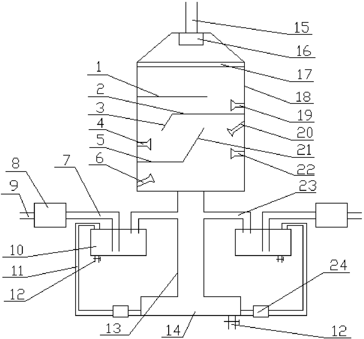
The invention provides a multi-stage exhaust gas treatment device. The exhaust gas treatment device comprises bag-type dust collectors, filter tanks, a collection box and a spray purifying tank, the bottom end of the spray purifying tank is connected with the collection box through a main pipe, two filter tanks are arranged and symmetrically located on both sides of the main pipe, the positions, close to the main pipe, of the filter tanks are communicated with the main pipe through air outlet pipes, and the positions, away from the main pipe, of the filter tanks are connected with bag-type dust collectors through air inlet pipes. According to the exhaust gas treatment device, exhaust gas is treated by adopting a multi-stage treatment manner of the bag-type dust collectors, the filter tanksand the spray purifying tank, the absorption rate of the exhaust gas can be improved, and the industrial discharge standard can be achieved; through special design of internal structures of the spraypurifying tank and ingenious combination of sprinkle heads and partition plates, the sprayed water is reflected by the partition plates, and the exhaust gas is in contact with the water repeatedly toimprove purification efficiency; through the arrangement of circulating pipelines and the collection box, the sprayed water is effectively recycled and reused, the use cost of water is reduced, and the purpose of green environmental protection is achieved.

Description

technical field [0001] The invention belongs to the field of environmental protection, and in particular relates to a multi-stage waste gas treatment device. Background technique [0002] Industrial waste gas refers to the general term for all kinds of pollutant gases that are discharged into the air during fuel combustion and production processes in the factory area. From the morphological analysis, industrial waste gas can be divided into particulate waste gas and gaseous waste gas. If these exhaust gases are discharged into the air without treatment, they will definitely have an impact on the environment. Among them, gaseous waste gas is the most diverse and most harmful industrial waste gas. Nitrogen-containing exhaust gas: This type of exhaust gas will damage the air components and change the gas composition ratio. Especially the combustion of petroleum products, the amount of combustion of petroleum products in industrial production is huge, and the content of nitro...

Claims


Application Information

Patent Timeline
IPC IPC(8): B01D53/78B01D53/50B01D46/02
CPCB01D46/02B01D53/504
Inventor 李艳忠
Owner 李艳忠
Learn More