Flue gas dedusting device and dedusting process

A dust removal device and flue gas technology, applied in solid separation, external electrostatic separators, chemical instruments and methods, etc., can solve problems such as waste of water resources, unsatisfactory discharge, and failure of bag dust removal.

Active Publication Date: 2021-01-26
MAANSHAN IRON & STEEL CO LTD
View PDF14 Cites 3 Cited by
  • Summary
  • Abstract
  • Description
  • Claims
  • Application Information

AI Technical Summary

Problems solved by technology

[0002] At present, wet dedusting systems are mostly used at home and abroad for drying flue gas, but the efficiency of wet dedusting systems is low, and the emission is difficult to meet the existing national standards, and the sediment discharged from wet dedusters needs to be treated, and the clarified washing water should be reused , otherwise it will not only cause secondary pollution, but also cause waste of water resources
Wastewater generated by wet dedusting requires a separate wastewater treatment system, which requires high operating and investment costs
If the bag-type dust removal system is used for drying flue gas, it can meet the national dust emission standards. However, due to the large amount of water vapor in the flue gas, the water vapor is prone to condensation due to temperature changes, which is likely to cause blockage of the bag dust removal filter bag, and the flue gas circulation effect is poor. Finally, the bag filter fails, so the bag filter is difficult to apply here
[0003] The use of electrostatic precipitator technology can effectively prevent the generation of sewage and avoid water pollution incidents; but the high moisture content of flue gas and large fluctuations in flue gas temperature are also unfavorable to the use of electrostatic precipitators, and the stability is poor
[0004] To sum up, the dust control of drying flue gas is a difficult problem in air pollution control, and the existing dust removal device and dust removal process have not effectively solved this problem

Method used


Image

  • Flue gas dedusting device and dedusting process

Examples


Embodiment Construction

[0023] The specific implementation manner of the present invention will be described in further detail below by describing the embodiments with reference to the accompanying drawings.

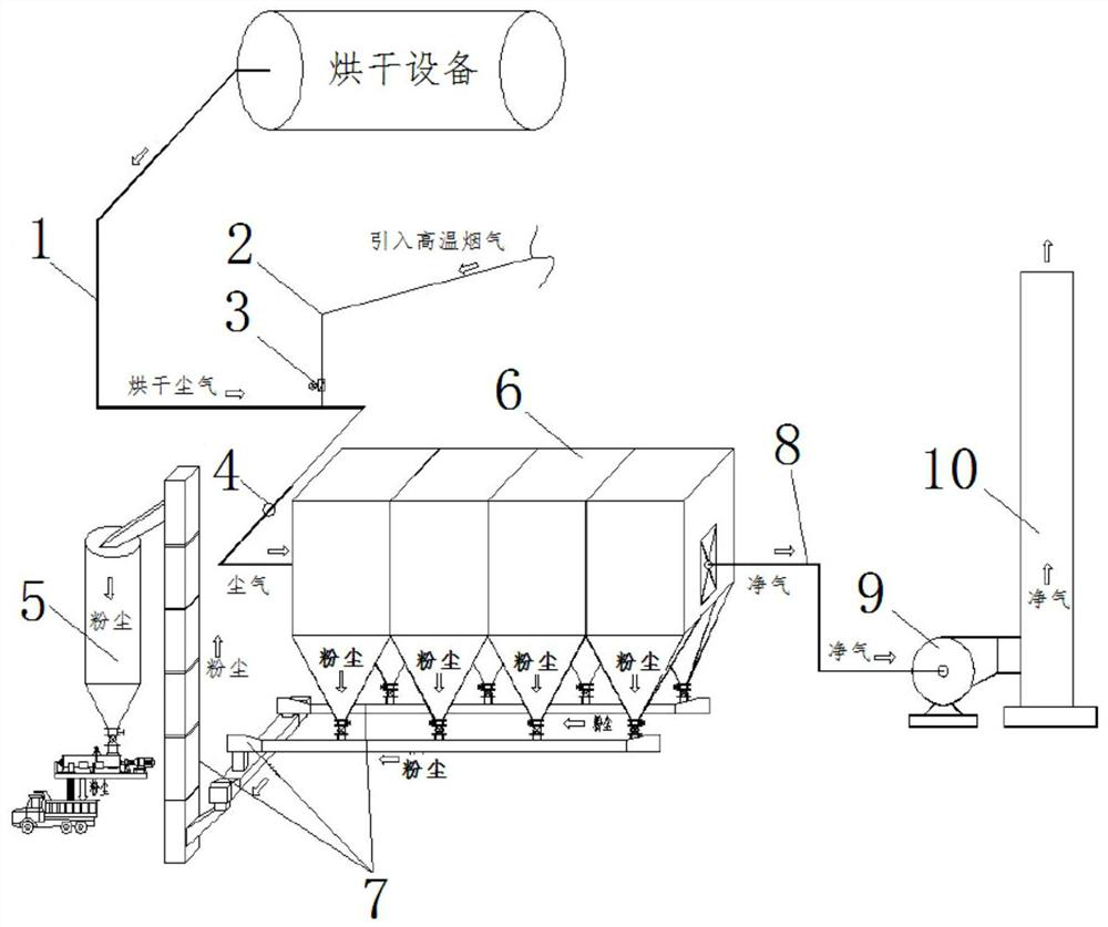
[0024] like figure 1 As shown, the flue gas dust removal device includes an air inlet flue 1, a hot air pipe 2, a regulating valve 3, a thermocouple 4, a powder bin 5, an electric dust collector 6, ash conveying equipment 7, an air outlet pipe 8, and a fan 9 and a chimney 10 .

[0025] The hot air pipe 2 is used to introduce high-temperature flue gas. The drying equipment is installed on the air inlet flue. The air outlet pipe is connected with the chimney through the fan.

[0026] The air inlet flue 1 is connected to the inlet of the electrostatic precipitator 6, and the hot air pipe is connected to the air inlet flue. Furthermore, the inlet of the electrostatic precipitator is connected with the air inlet flue through a section of dust removal pipeline. There is a certain distance between...


PUM


Abstract

The invention discloses a flue gas dedusting device, which includes an air inlet flue, an electric precipitator, a fan and a chimney, and also includes drying equipment and a hot air pipe for introducing high-temperature flue gas. The drying equipment is arranged at the inlet On the air flue, the air inlet flue and the hot air pipe are connected with the inlet of the electrostatic precipitator, and the outlet of the electrostatic precipitator is connected with the chimney through the fan. The flue gas dust removal process includes the following steps: 1) The dust gas dried by the drying equipment is mixed with the high-temperature flue gas introduced through the hot air pipe into the electrostatic precipitator; 2) The electric field wind speed in the electrostatic precipitator is controlled at 0.6-1.5 Between m / s; 3) The dust is collected by the electrostatic precipitator and transported to the powder bin through the ash conveying equipment, and the purified flue gas is discharged through the fan and the chimney. Ensure stable and up-to-standard emission of dust and safe operation.

Description

technical field [0001] The invention relates to the technical field of flue gas dust removal, in particular to a flue gas dust removal device and a dust removal process thereof. Background technique [0002] At present, wet dedusting systems are mostly used at home and abroad for drying flue gas, but the efficiency of wet dedusting systems is low, and the emission is difficult to meet the existing national standards, and the sediment discharged from wet dedusters needs to be treated, and the clarified washing water should be reused Otherwise, it will not only cause secondary pollution, but also cause waste of water resources. Wastewater generated by wet dedusting requires a separate wastewater treatment system, which requires high operating and investment costs. If the bag-type dust removal system is used for drying flue gas, it can meet the national dust emission standards. However, due to the large amount of water vapor in the flue gas, the water vapor is prone to condens...

Claims


Application Information

Patent Timeline
Patent Type & Authority Patents(China)
IPC IPC(8): B03C3/014B03C3/04
CPCB03C3/014B03C3/04
Inventor 唐胜卫程黄根曹超黄鹏贾红芳汪为民杨文武
Owner MAANSHAN IRON & STEEL CO LTD
Why Eureka
Try Eureka