Damper damping mechanism and hydraulic-pneumatic combined damping damper applied same
A technology of damping mechanism and air pressure combination, applied in the direction of shock absorber, spring/shock absorber, shock absorber, etc., can solve the problem of strong pressing impact, poor rebound damping effect, long shock absorber movement, etc. problem, to achieve the effect of improving the rebound damping effect and the outstanding damping effect
- Summary
- Abstract
- Description
- Claims
- Application Information
AI Technical Summary
Problems solved by technology
Method used
Image
Examples
Embodiment 1
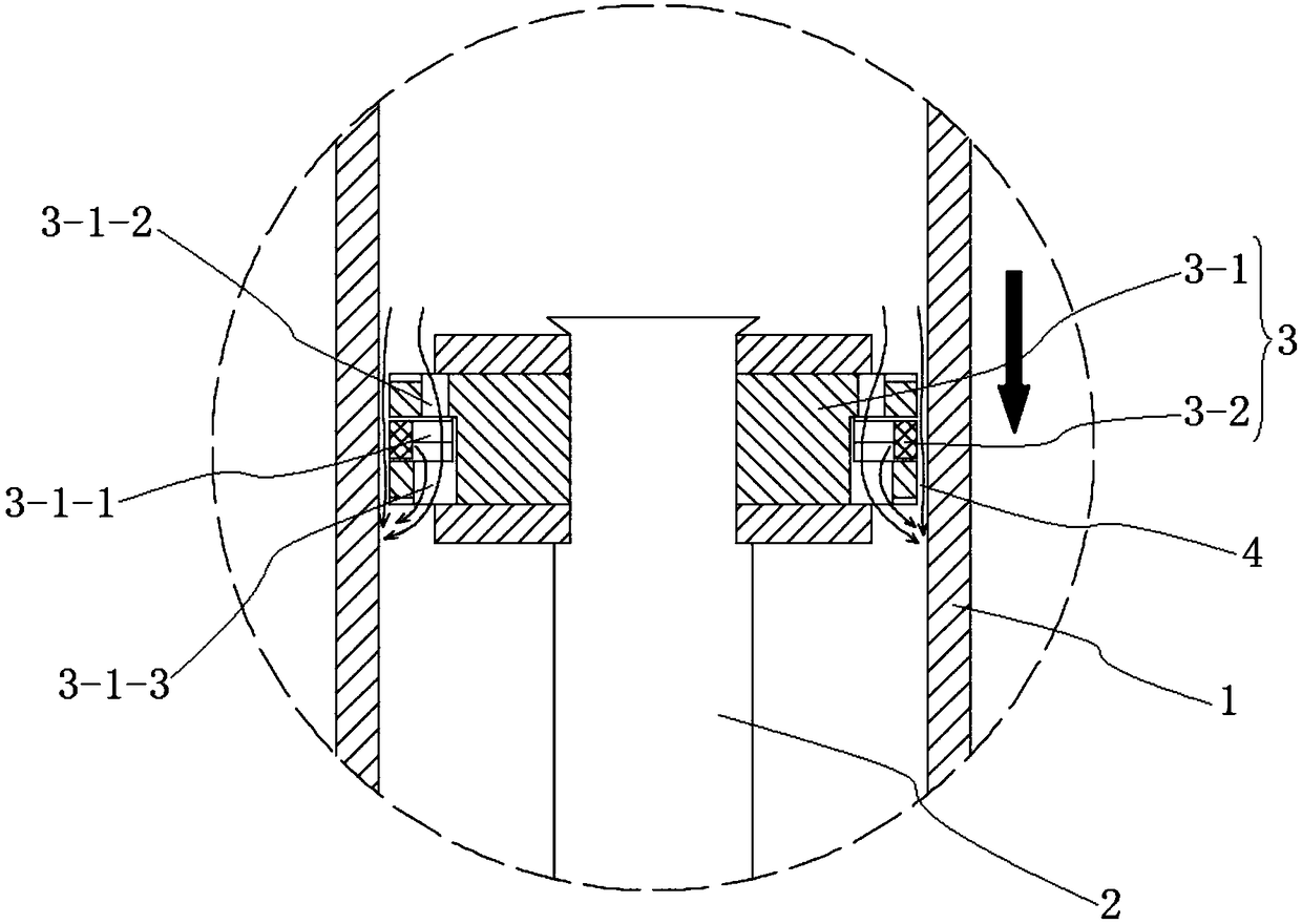
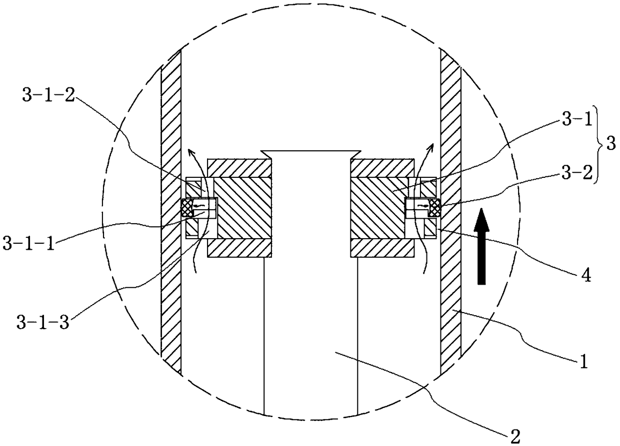
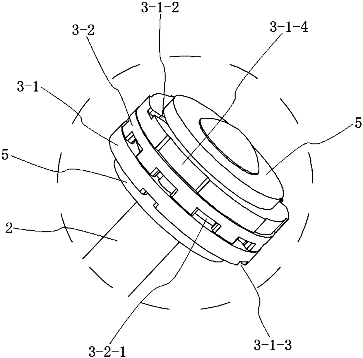
[0037] combine figure 1 and figure 2 As shown, a shock absorber damping mechanism of this embodiment includes a handle tube 1, a piston rod 2 and a damping piston 3 arranged on the piston rod 2. The damping piston 3 is located in the handle tube 1, and the handle tube 1 is divided into The rodless cavity and the rod cavity, the damping piston 3 and the handle tube 1 have a gap fit, so that there is a gap 4 for the damping medium to flow between the outer wall of the damping piston 3 and the inner wall of the handle tube 1, and the pressure on the handle tube 1 At the same time, part of the damping medium flows through the damping hole to produce a damping effect, and at the same time, part of the damping medium flows through the gap 4 between the damping piston 3 and the handle tube 1, which effectively solves the problem of the shock feeling caused by the fact that the damping medium cannot flow quickly at the moment of pressing down question. The damping piston 3 includes...
Embodiment 2
[0042] combine Image 6 As shown, this embodiment discloses a hydraulic-pneumatic combined damping shock absorber using the shock absorber damping mechanism described in the above-mentioned embodiment 1, which includes a sleeve 8, a handle 1, a piston rod 2 and a The damping piston 3 on the rod 2, the specific structure of the handle tube 1 and the damping piston 3 are the same as in the embodiment 1, the handle tube 1 is arranged in the casing 8, and the guide and sealing cooperation between the handle tube 1 and the casing 8 forms a sealed The air pressure chamber, specifically, a guide sealing assembly 9 can be set at the opening position of the casing 8 to ensure the sealing of the air pressure chamber; the end of the piston rod 2 passing through the handle pipe 1 is fixed on the bottom of the casing 8 through the hanging bolt 11, and the piston rod 2 and the The end of the handle tube 1 is also matched by a guide seal; the rodless cavity of the handle tube 1 is provided w...
PUM
 Abstract
Description
Claims
Application Information
 - R&D
- Intellectual Property
- Life Sciences
- Materials
- Tech Scout
- Unparalleled Data Quality
- Higher Quality Content
- 60% Fewer Hallucinations
Browse by: Latest US Patents, China's latest patents, Technical Efficacy Thesaurus, Application Domain, Technology Topic, Popular Technical Reports.
© 2025 PatSnap. All rights reserved.Legal|Privacy policy|Modern Slavery Act Transparency Statement|Sitemap|About US| Contact US: help@patsnap.com


