A kind of manufacturing method of cone enveloping cone worm pair

A manufacturing method and technology of a tapered worm, which is applied in the directions of worms, worm gears, components with teeth, etc., can solve the problems of unsatisfactory meshing ability of two sides of a tooth and so on.

Inactive Publication Date: 2020-10-27
NORTHEASTERN UNIV LIAONING
View PDF3 Cites 0 Cited by
  • Summary
  • Abstract
  • Description
  • Claims
  • Application Information

AI Technical Summary

Problems solved by technology

In addition, the ability to control the asymmetry of meshing between the sides of a tooth is not ideal for classic bevel-worm drives

Method used


Image

  • A kind of manufacturing method of cone enveloping cone worm pair
  • A kind of manufacturing method of cone enveloping cone worm pair
  • A kind of manufacturing method of cone enveloping cone worm pair

Examples


Embodiment 1

[0115] In this embodiment, the enveloping cone worm 1 rotates right, and the number of heads is Z 1 =1, the secondary axis of the cone enveloping cone worm is non-orthogonal, and the axis angle Σ=75°, the manufacturing method of this embodiment adopts the following steps:

[0116] Step 1. Set the coordinate parameters of the enveloping cone worm to be manufactured:

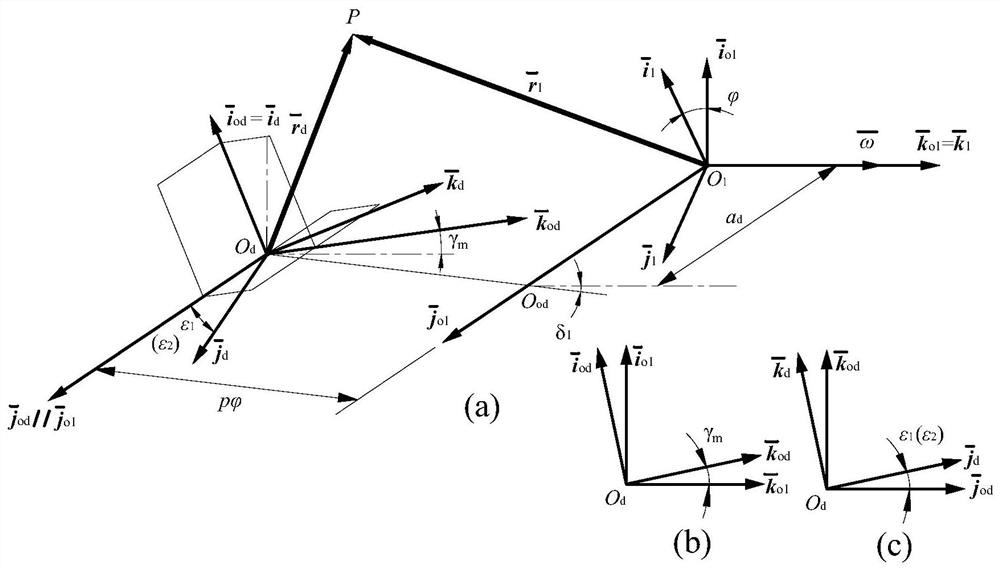
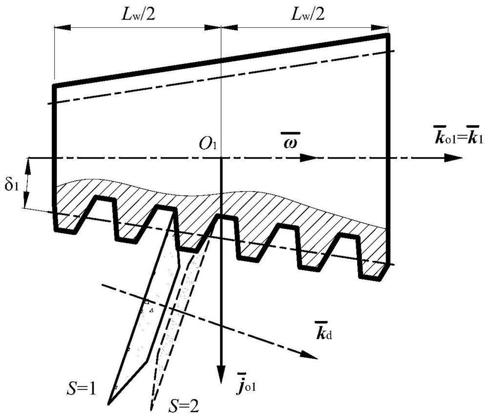
[0117] Conical Worm Blank and Moving Coordinate System The phases are fixed, the moving coordinate system σ 1 The unit basis vector of From the small end to the large end along the axis of the conical worm blank, the moving coordinate system σ 1 The coordinate origin O 1 Located on the axis of the bevel worm blank, is the thread length L of the enveloping bevel worm w the midpoint of

[0118]The static coordinate system of the cone worm blank is Static coordinate system σ o1 The unit basis vector of and the moving coordinate system σ 1 The unit basis vector of Coincident, along the axis of the beve...

Embodiment 2

[0168] The manufacturing method of the cone-enveloping cone-worm pair of this embodiment is the same as that of Embodiment 1, but the basic parameters and processing parameters of the cone-enveloping cone-worm pair are different.

[0169] The enveloping cone worm in this embodiment is right-handed, and the number of heads is Z 1 = 3, the two axes of the cone enveloping cone and worm pair are orthogonal, that is, the axis angle Σ = 90°, the center distance a = 100mm, the transmission ratio i 12 =18, according to the formula provided by the present invention, it can be estimated that the modulus of the enveloping cone worm along the sub-cone generatrix is:

[0170]

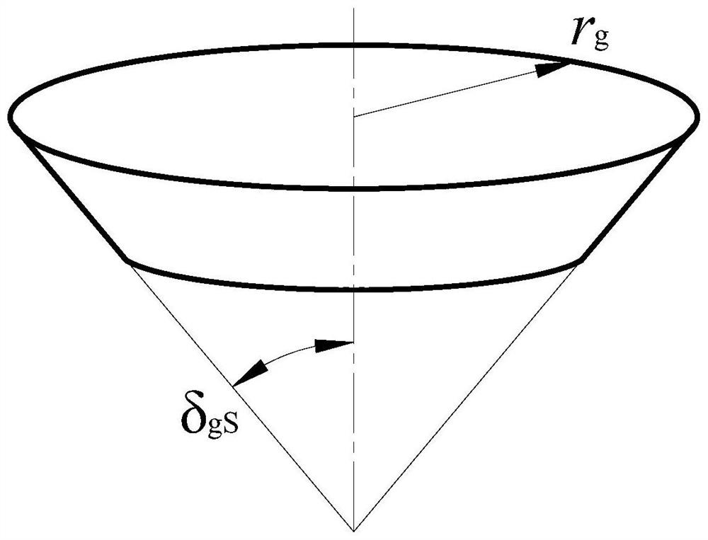
[0171] rounded to a standard value, take m δ =4mm; Enveloping cone worm length L w =0.73a=0.73×100=73mm, the lead angle γ of the enveloping cone worm at the reference point M m =15.818°, enveloping cone worm sub-cone angle δ 1 =5°, the radius r of the dedendum circle at the midpoint of the enveloping cone wor...


PUM

PropertyMeasurementUnit
lengthaaaaaaaaaa

Abstract

The invention relates to a conical surface enveloping cone worm pair and a manufacturing method thereof, and belongs to the technical field of offset worm transmission. The conical surface envelopingcone worm pair comprises an enveloping cone worm and a cone worm wheel, the spiral surface of the enveloping conical worm is an expandable curved surface, the expandable curved surface is ground to beformed by the disc-shaped conical surface grinding wheel, and the enveloping cone worm is meshed with the bevel gear wheel; the conical surface enveloping cone worm pair is suitable for occasion of axis orthogonal staggered or axis non-orthogonal staggered with the transmission ratio of i 12 being greater than or equal to 10; and the manufacturing method of the conical surface enveloping cone worm pair comprises the following steps that 1, coordinate parameters of a to-be-manufactured enveloping cone worm are set, 2, the enveloping conical worm is manufactured, 3, the coordinate parameters ofthe to-be-manufactured are set, 4, a cone worm wheel is manufactured, and 5, the conical surface enveloping cone worm pair is assembled. The tooth surfaces of the conical surface enveloping cone wormpair are not prone to causing curvature interference, the number of the suitable worms is multiple, the range of the transmission ratio is wide, the distribution of the instantaneous contact lines isuniform, sparse and cross-free, heat dissipation and lubrication are facilitated, the bearing capacity is high, the transmission efficiency is high, and the service life is long.

Description

technical field [0001] The invention relates to the technical field of offset worm transmission, in particular to a method for manufacturing a cone enveloping cone worm pair. Background technique [0002] The helical surface of the classic cone-worm screw is formed by turning with a straight-edge turning tool. It is a non-developable ruled surface, and it is difficult to precisely grind according to the forming principle. This is not conducive to the finishing of the helical surface of the bevel worm after hardening, and is also not conducive to further improving the load-carrying capacity of the transmission pair. The meshing boundary of the classic bevel-worm drive may enter the bevel-worm tooth flank, thereby creating an unusable zone, and this part of the corresponding bevel-worm gear face will cause the mating bevel-worm gear tooth flank to undercut. Furthermore, the ability to control the asymmetry of the flank meshing of a tooth is not ideal for a classic bevel-worm ...

Claims


Application Information

Patent Timeline
Patent Type & Authority Patents(China)
IPC IPC(8): F16H55/22F16H55/08B23F13/00B23F11/00
CPCB23F11/00B23F13/006F16H55/08F16H55/22
Inventor 赵亚平孟庆祥孔祥伟
Owner NORTHEASTERN UNIV LIAONING
Why Eureka
Try Eureka