Integrated grain barn structure for drying and storing grains

A granary and drying technology, which is applied in the direction of drying solid materials, local agitation dryers, and static material dryers, etc., can solve the problems of low drying efficiency, cumbersome drying process, and uneven drying, so as to improve efficiency and speed up diffusion , Improve the effect of drying efficiency

Inactive Publication Date: 2018-09-04
ZHENGZHOU LONGWEI ELECTRONICS TECH CO LTD
View PDF5 Cites 0 Cited by
  • Summary
  • Abstract
  • Description
  • Claims
  • Application Information

AI Technical Summary

Problems solved by technology

[0004] In view of this, this application provides an integrated granary structure for drying and storing grains, which solves the problems of cumbersome grain drying process, uneven drying, and...

Method used


Image

  • Integrated grain barn structure for drying and storing grains

Examples


Embodiment 1

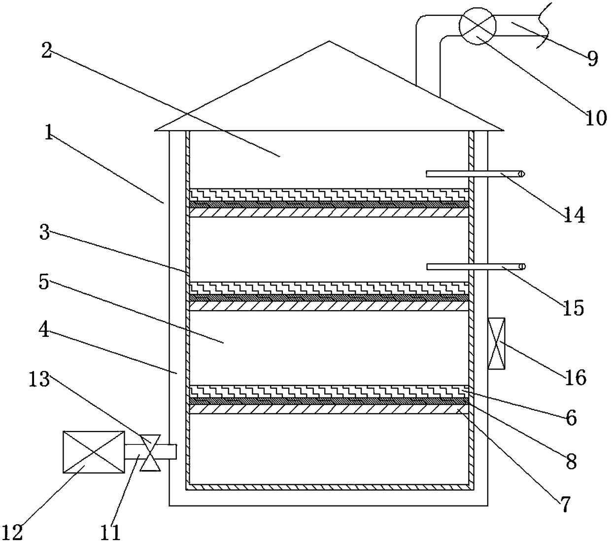
[0018] like figure 1 The shown integrated granary structure for dry grain storage includes a granary body 1, and a grain storage cavity 2 is arranged inside the granary body 1, and the cavity wall 3 of the grain storage cavity 2 is a mesh structure, and the mesh structure The mesh size of the structure is not larger than the particle diameter of the grain. A gas channel 4 is formed between the grain storage chamber 2 and the inner wall of the granary body 1. The gas channel 4 is connected with an air intake device communicating with the outside of the granary. The grain storage cavity 2 includes a plurality of grain storage units 5 arranged up and down, and a drying device is arranged between adjacent grain storage units 5, and the drying device includes a mesh partition and a drying mechanism 6 located on the mesh partition. , the mesh aperture of the mesh partition is not larger than the grain diameter, and the drying mechanism 6 is any one of a microwave dryer or an electri...

Embodiment 2

[0021] Based on Example 1, such as figure 1 As shown, the mesh partition includes a porous plate 7 and a filter screen 8 located on the porous plate 7, and the aperture of the filter screen 8 is not larger than the particle size of the grain. Through the arrangement of the perforated plate 7 and the filter screen 8 , while ensuring the stability of the grain storage unit 5 , a gas diffusion channel is formed between the grain storage units 5 to improve the drying efficiency.

Embodiment 3

[0023] Based on Example 1, such as figure 1 As shown, the exhaust device includes an exhaust pipe 9 communicating with the interior of the grain storage chamber 2, and an induced draft fan 10 is arranged on the exhaust pipe 9. Through the arrangement of the induced draft fan 10, the diffusion speed of the gas can be accelerated, and the efficiency of drying and dehumidification can be further improved.


PUM


Abstract

The invention provides an integrated grain barn structure for drying and storing grains. The integrated grain barn structure for drying and storing the grains comprises a grain barn body, wherein a grain storage chamber is arranged in the grain barn body; a chamber wall of the grain storage chamber is of a mesh-shaped structure; the mesh hole size of the mesh-shaped structure is not larger than the grain particle size; an air channel is formed between the grain storage chamber and an inner wall of the grain barn body; an air inlet channel communicating with the outer part of the grain barn isconnected onto the air channel; the grain storage chamber comprises multiple grain storage units arranged up and down; a drying device is arranged between each two adjacent grain storage units, and comprises a mesh-shaped clapboard and a drying mechanism located on the mesh-shaped clapboard; the mesh hole diameter of each mesh-shaped clapboard is not larger than the grain particle size; and an airdischarge device communicating with the outer part of the grain barn body is further arranged on the upper part of the grain storage chamber. The integrated grain barn structure for drying and storing the grains solves the problems that an existing grain drying process is complicated, the grains cannot be dried uniformly, and the drying efficiency is low due to a moisture gradient, the integration of drying and grain storing can be realized, the drying efficiency is improved, and meanwhile, a drying and grain storing process is simplified.

Description

technical field [0001] The invention relates to the technical field of grain storage equipment, in particular to an integrated grain silo structure for dry grain storage. Background technique [0002] Grain is an important material for the national economy and the people's livelihood. The moisture contained in the grain needs to be dried to the required humidity value before it can be stored safely. When the dried grain is stored in the granary, the humidity in the granary will increase due to the long storage time and weather changes. If the granary is not dried in time, the humidity in the granary will drop. It will make the grain mildew and cause the grain to deteriorate. Even if the grain storage with low water content is poor, if the ventilation effect of the granary is not good, the storage time will affect the storage quality of the grain. [0003] Grain drying is a process that consumes a lot of energy. High-moisture grain drying usually uses coal as fuel, and a dry...

Claims


Application Information

Patent Timeline
IPC IPC(8): F26B9/06F26B23/04F26B23/08F26B25/00A01F25/14
CPCA01F25/14F26B9/06F26B23/04F26B25/00
Inventor 赵峰
Owner ZHENGZHOU LONGWEI ELECTRONICS TECH CO LTD
Why Eureka
Try Eureka