A motor with braking energy recovery function for new energy vehicles
What is Al technical title?
Al technical title is built by PatSnap Al team. It summarizes the technical point description of the patent document.
A braking energy recovery, new energy vehicle technology, applied in the direction of motors, electric vehicles, electric braking systems, etc., can solve the problems of motor short-circuit burnout and large motor energy consumption, so as to prevent short-circuit burnout and reduce unit energy consumption , good dehumidification effect
Active Publication Date: 2020-02-11
瑞安市本富机电设备有限公司
View PDF2 Cites 0 Cited by
Summary
Abstract
Description
Claims
Application Information
AI Technical Summary
This helps you quickly interpret patents by identifying the three key elements:
Problems solved by technology
Method used
Benefits of technology
Problems solved by technology
[0003] Existing motors generally prevent the internal structure of the motor from being damaged due to excessive expansion of the air inside the motor by setting vents, but water, mud or foreign matter can easily enter the motor from the vents, causing existing motors to Not only that, when the vehicle decelerates, the existing motor needs to quickly reduce the speed and convert the kinetic energy of the motor rotor into heat energy, so that the vehicle cannot recover the kinetic energy of the motor rotor when braking or coasting, resulting in Some motors consume more energy
Method used
Image
Click on the blue label to locate the original text in one second.
Reading with bidirectional positioning of images and text.
Examples
Embodiment Construction
[0027] The present invention is described in further detail now in conjunction with accompanying drawing. These drawings are all simplified schematic diagrams, which only illustrate the basic structure of the present invention in a schematic manner, so they only show the configurations related to the present invention.
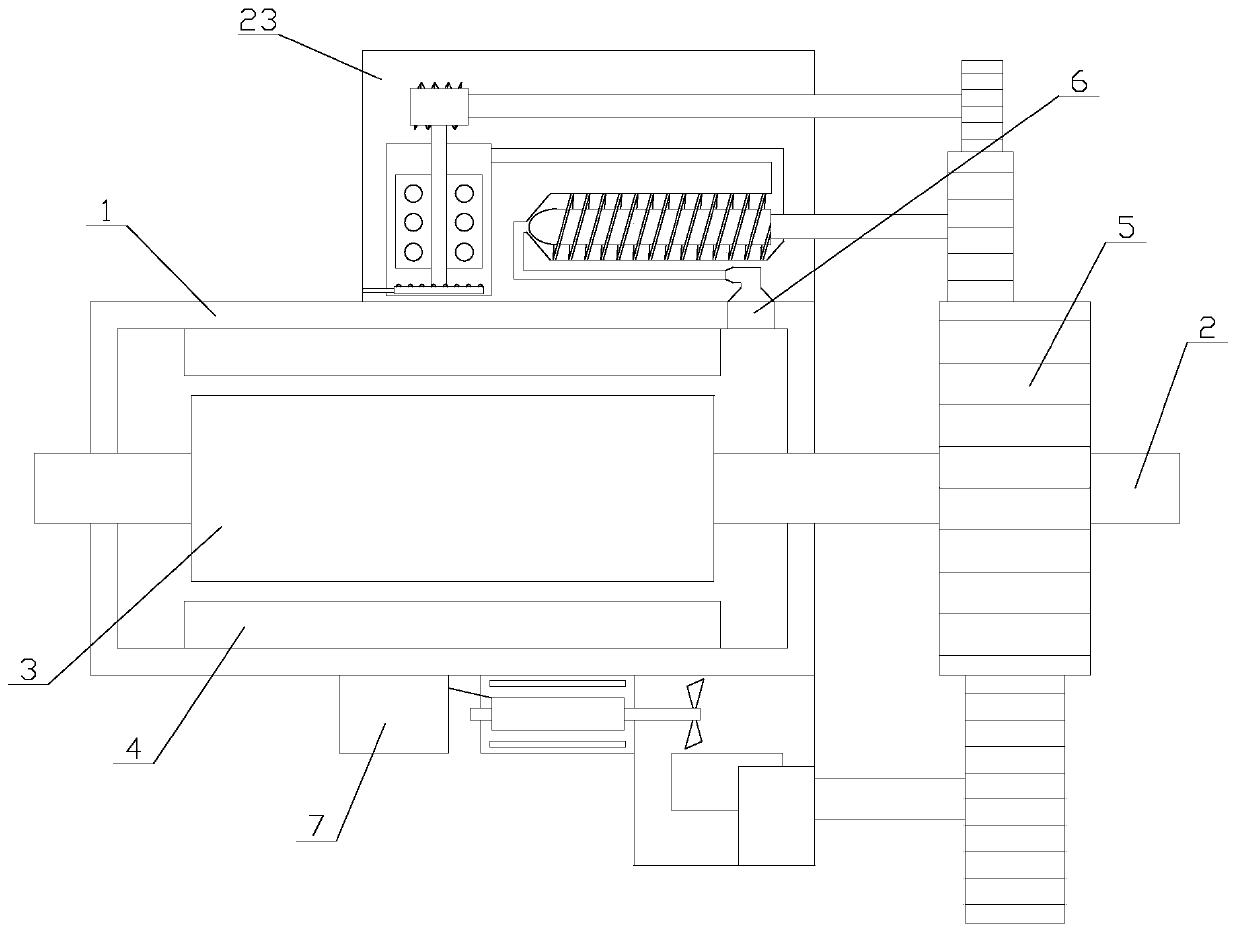
[0028] Such as figure 1 As shown, a motor with braking energy recovery function for new energy vehicles includes a main body 1, an output shaft 2, a first gear 5, a recovery mechanism and a dust removal box 23, and one end of the output shaft 2 passes through the main body 1. The output shaft 2 is fixedly connected with the first gear 5, the output shaft 2 and the first gear 5 are coaxially arranged, the recovery mechanism is arranged under the main body 1, and the dust removal box 23 is fixed on the side of the main body 1 Above, the main body 1 is provided with a PLC, the rotor 3 and the stator 4, the dust removal box 23 is provided with a dust removal mech...
PUM
Abstract
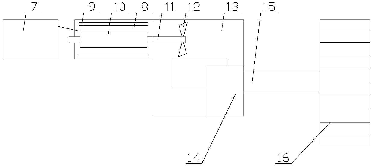
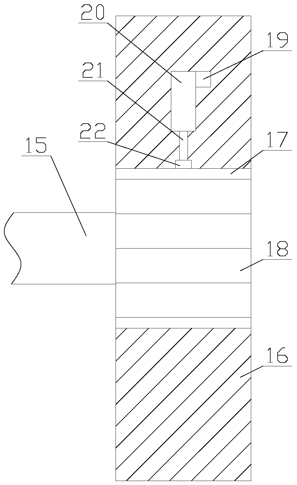
The invention relates to a motor with a braking energy recovery function for a new energy vehicle. The motor comprises a main body, an output shaft, a first gear, a recycling mechanism and a dust removing box. The main body is internally provided with a PLC, a rotor and a stator. The dust removing box is internally provided with a dust removing mechanism. The recycling mechanism comprises a storage battery, a casing, a rotating shaft, a return pipe, a compressor, a connecting rod, a second gear and a plurality of blades. A control unit is arranged in the second gear. The dust removing mechanism comprises a dust cleaning unit, a drying pipe, a drying chamber and an air intake unit, and the air intake unit includes a third gear, a rotating rod, a roller, a thread, an air intake pipe and a communication pipe. According to the motor with a braking energy recovery function for a new energy vehicle, through the recycling mechanism, the kinetic energy of the rotor of the motor is recovered and stored in the storage battery in braking or coasting, and the unit energy consumption of the motor is reduced. Moreover, the dust removing mechanism can prevent water, mud or foreign matter from entering the inside of the motor from a vent hole, and the motor is prevented from being short-circuited and burned.
Description
technical field [0001] The invention relates to the field of new energy vehicles, in particular to a motor for new energy vehicles with a braking energy recovery function. Background technique [0002] New energy vehicles refer to the use of unconventional vehicle fuels as power sources (or the use of conventional vehicle fuels, the use of new vehicle power devices), integrated vehicle power control and advanced technology in driving, the formation of advanced technical principles, with The motor is the power source of new energy vehicles and the most important part of new energy vehicles. [0003] Existing motors generally prevent the internal structure of the motor from being damaged due to excessive expansion of the air inside the motor by setting vents, but water, mud or foreign matter can easily enter the motor from the vents, causing existing motors to Not only that, when the vehicle decelerates, the existing motor needs to quickly reduce the speed and convert the kin...
Claims
Application Information
Patent Timeline
Application Date:The date an application was filed.
Publication Date:The date a patent or application was officially published.
First Publication Date:The earliest publication date of a patent with the same application number.
Issue Date:Publication date of the patent grant document.
PCT Entry Date:The Entry date of PCT National Phase.
Estimated Expiry Date:The statutory expiry date of a patent right according to the Patent Law, and it is the longest term of protection that the patent right can achieve without the termination of the patent right due to other reasons(Term extension factor has been taken into account ).
Invalid Date:Actual expiry date is based on effective date or publication date of legal transaction data of invalid patent.