
Switching power supply

A switching power supply and output voltage technology, applied in the direction of electrical components, output power conversion devices, etc., can solve the problem that the phase-frequency characteristics and amplitude-frequency characteristics cannot match the user, and achieve the improvement of the phase-frequency characteristics and amplitude-frequency characteristics of the Bode diagram Effect

Pending Publication Date: 2018-09-04
SHENZHEN GOLD POWER TECH
View PDF0 Cites 1 Cited by
  • Summary
  • Abstract
  • Description
  • Claims
  • Application Information

AI Technical Summary

Problems solved by technology

[0005] Aiming at the deficiency that the phase-frequency characteristics and amplitude-frequency characteristics of the Bode diagram of the current switching power supply cannot match the expectations of users, the present invention proposes a switching power supply circuit, which has good phase-frequency characteristics and amplitude-frequency characteristics of the Bode diagram

Method used


Image

  • Switching power supply
  • Switching power supply
  • Switching power supply

Examples


Embodiment 1

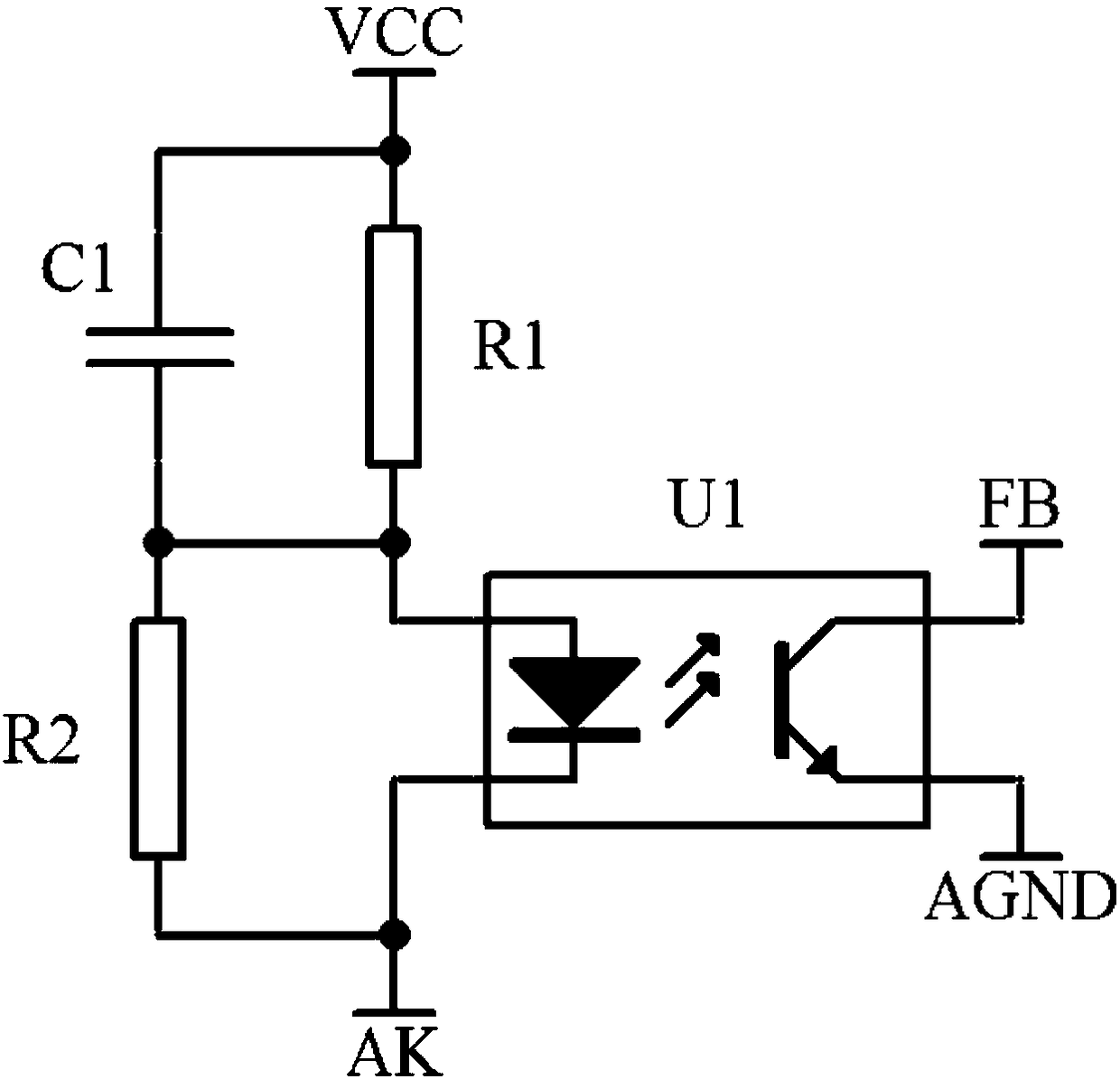
[0013] Example 1, as figure 2 Shown is the isolated feedback circuit of the switching power supply in this embodiment, such as figure 1 As shown, this isolated feedback circuit is an isolated feedback loop, including optocoupler U1, current limiting resistor R1, and voltage dividing resistor R2; the output voltage VCC is connected to the anode of the primary diode of optocoupler U1 through the current limiting resistor R1, and the voltage dividing resistor R2 One end of the optocoupler U1 is connected to the anode of the primary diode of the optocoupler U1, the negative electrode of the optocoupler U1 primary diode and the other end of the voltage dividing resistor R2 are connected to the compensation and feedback control end of the switching power supply feedback circuit; the C pole of the secondary side triode of the optocoupler U1 is connected to the control At the feedback signal input end of the circuit, the secondary side transistor E of the optocoupler U1 is connected...


PUM


Abstract

The invention provides a switching power supply comprising an isolated feedback loop for feeding back an output voltage VCC to a control circuit. The isolated feedback loop consists of an optocouplerU1, a current-limiting resistor R1, and a voltage-dividing resistor R2. The output voltage VCC is connected to the anode of a primary-side diode of the optocoupler U1 through the current-limiting resistor R1; one end of the voltage-dividing resistor R2 is connected with the anode of the primary-side diode of the optocoupler U1; and a cathode of the primary-side diode of the optocoupler U1 and theother end of the voltage-dividing resistor R2 are connected with a compensation and feedback control terminal of a switching power supply feedback circuit. A C pole of a secondary-side triode C of theoptocoupler U1 is connected to a feedback signal input terminal of a control circuit; and an E pole of the secondary-side triode C of the optocoupler U1 is connected with a secondary side ground. Inaddition, the switching power supply also includes a capacitor C1; and the two poles of the capacitor C1 are connected with two ends of the current-limiting resistor R1. Because the capacitor C1 is arranged at the voltage-dividing resistor of the optocoupler in the feedback circuit of the switching power supply, the phase-frequency characteristic and the amplitude-frequency characteristic of the Bode diagram of the switching circuit are significantly improved.

Description

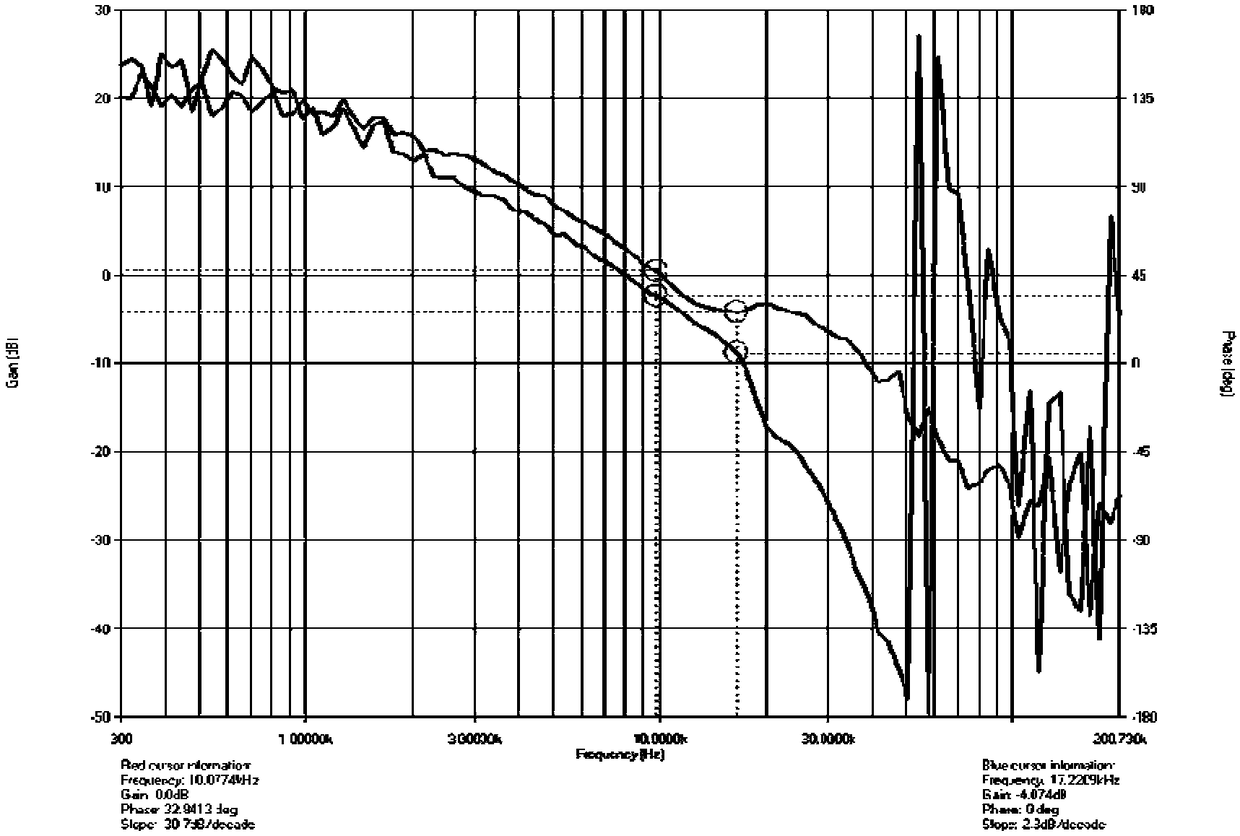
technical field [0001] The invention relates to the field of switching power supplies, in particular to a switching circuit with an improved Bode plot. Background technique [0002] The Bode plot is a semi-logarithmic coordinate plot of a linear time-invariant transfer function versus frequency. The horizontal axis represents the frequency and the vertical axis represents the amplitude. The Bode plot can be used to see the frequency response of the system. Pod Figure 1 Generally, it is composed of two graphs, an amplitude-frequency graph, which shows the change of the decibel value of the frequency response gain against the frequency, and a phase-frequency graph, which is the change of the phase of the frequency response to the gain. The switching power supply industry usually tests the Bode plot to judge the stability of the feedback circuit. The Bode plot test method is to add interference signals of different frequencies to the feedback circuit to test the phase-frequenc...

Claims


Application Information

Patent Timeline
Patent Type & Authority Applications(China)
IPC IPC(8): H02M1/00
CPCH02M1/00H02M1/0003
Inventor 陈智彬蒋中为
Owner SHENZHEN GOLD POWER TECH
Learn More