[0040] In order to be able to understand the above objectives, features and advantages of the present invention more clearly, the present invention will be further described in detail below in conjunction with the accompanying drawings and specific embodiments. It should be noted that the embodiments of the application and the features in the embodiments can be combined with each other if there is no conflict.
[0041] In the following description, many specific details are set forth in order to fully understand the present invention. However, the present invention can also be implemented in other ways different from those described here. Therefore, the protection scope of the present invention is not covered by the specific implementations disclosed below. Limitations of cases.
[0042] Hereinafter, cooking appliances according to some embodiments of the present invention will be described with reference to the accompanying drawings.
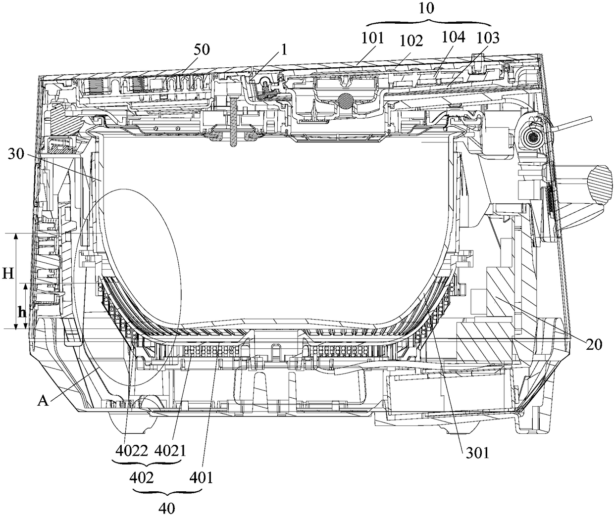
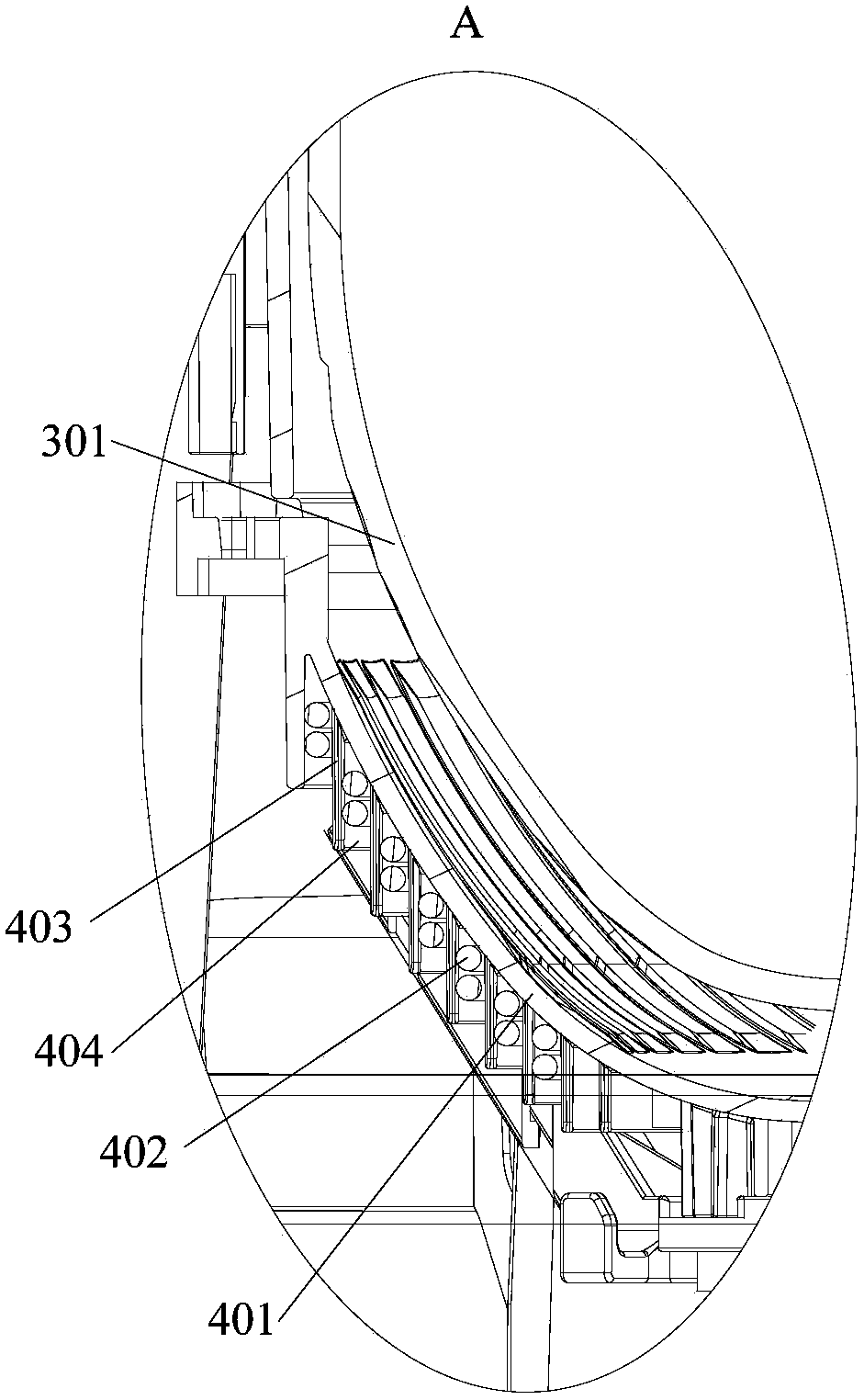
[0043] Such as figure 1 with figure 2 As shown, according to some embodiments of the present invention, a cooking appliance is provided. The cooking appliance includes a pot body and an upper cover 1. The upper cover 1 is covered on the pot body, the upper cover 1 is provided with a steam valve 10, and the steam valve 10 covers at least 1/2 of the upper surface of the upper cover 1. The pot body includes an inner pot 30 and is located under the inner pot 30 On the side of the coil disk 40, the inner pot 30 includes a side wall, a bottom wall, and an arc position 301 of the inner pot connecting the side walls and the bottom wall. The coil disk 40 includes a disk body 401 and a multi-turn coil 402 wound on the disk body 401 , The plate 401 defines the accommodating space, the inner pot 30 is at least partially located in the accommodating space, and the uppermost coil 402 is located at 2/3 of the height of the inner pot arc 301 or 2/higher than the height of the inner pot arc 301. 3 locations.
[0044] In the cooking appliance provided by the above embodiment of the present invention, the steam valve 10 covers at least 1/2 of the upper surface of the upper cover 1, that is, the size of the steam valve 10 exceeds 1/2 of the size of the upper cover 1, which increases the volume of the inner cavity of the steam valve 10 It increases the flow distance of the steam in the steam valve 10, thereby significantly improving the anti-overflow performance of the cooking appliance during the cooking process, and solves the problem of poor anti-overflow ability caused by the small internal cavity of the steam valve 10; in the coil plate 40 The top coil 402 is not lower than 2/3 of the height of the arc position 301 of the inner pot, such as figure 1 As shown, h≥2/3H, a bowl-shaped accommodating space is formed. Compared with the disk-shaped accommodating space in the related art, the winding of the coil disk 40 can cover the inner pot 30 as much as possible, thereby increasing the The heating area of the inner pot achieves the effect of a hot bun pot similar to a wood-fired rice open-fire roasting pot, which can increase the firepower and enhance the taste of cooking without overflowing. Turn on the full power or high power heating mode in the boiling stage that requires high firepower or other stages that require high firepower to achieve high firepower heating. For example, when the rice is cooked in a rice cooker, the rice can be boiled to the core and the grains are full to achieve sweet and good rice .
[0045] Such as figure 1 with figure 2 As shown, the inner pot 30 includes a bottom wall, a side wall, and an inner pot arc position 301 connecting the periphery of the bottom wall and the side wall. The arrangement of the inner pot arc position 301 can form heat convection, making the entire thermal field more uniform and improving The uniformity of heating of rice grains everywhere.
[0046] Preferably, as figure 1 As shown, the disc body 401 is a concave disc body 401 adapted to the inner pot 30. The multi-turn coil 402 includes a first coil 4021 wound on the bottom of the concave disc body 401 and wound around the concave disc body 401 side. Section of the second coil 4022.
[0047] The tray 401 has a concave shape, thereby forming a bowl-shaped containing space, and the shape of the containing space is adapted to the bottom of the inner pot 30. The coil 402 includes at least one first coil 4021 wound on the bottom of the concave disk body 401 and at least one second coil 4022 wound on the side of the concave disk body 401, wherein the uppermost coil 402 of the second coil 4022 Located at the height of 2/3 of the arc position 301 of the inner pot or above the height of 2/3 of the arc position 301 of the inner pot.
[0048] Preferably, the winding densities of the first coil 4021 at the bottom of the concave disc body 401 and the second coil 4022 at the side of the concave disc body 401 can be different, so that strong heating is achieved where the winding density is high, and the winding density is low. Weak heating is realized at the place, of course, the winding density of the first coil 4021 and the second coil 4022 can also be the same.
[0049] Preferably, as figure 2 As shown, the outer surface of the disc body 401 protrudes to form a plurality of winding ribs 403, two adjacent winding ribs 403 form a winding groove 404, and the coil 402 is located in the winding groove 404.
[0050] For the concave disc body 401, the outer surface of the bottom and the outer surface of the side portion of the concave disc body 401 respectively protrude outward to form a plurality of winding ribs 403. The winding rib 403 may be vertical or horizontal.
[0051] Preferably, the steam valve 10 covers the entire upper surface of the upper cover 1.
[0052] For products where the control panel 50 is designed on the body of a cooking appliance such as an electric rice cooker, the steam valve 10 can cover the entire upper surface of the upper cover 1, thereby maximizing the size of the steam valve 10 and further improving the effect of preventing overflow .
[0053] Preferably, the upper cover 1 is provided with a steam valve assembly position for installing the steam valve 10, the steam valve assembly position has a left and right open assembly surface, and the left and right sides of the steam valve 10 are flush with the left and right edges of the assembly surface.
[0054] Further, the steam valve assembly position has an assembly surface with an open rear end, and the rear end surface of the steam valve 10 is flush with the rear end edge of the assembly surface.
[0055] The steam valve assembly position has an assembly surface with left and right openings and an open rear end, which avoids the problem that the size of the steam valve 10 cannot be enlarged due to the space limitation of the steam valve assembly position. Therefore, by increasing the size of the steam valve 10, a good Anti-overflow effect and easy to clean the assembly position of the steam valve; preferably, the left and right sides of the steam valve 10 are designed to be flush with the left and right edges of the assembly surface, and the rear end of the steam valve 10 is flush with the rear edge of the assembly surface, effectively ensuring The overall appearance of the upper cover 1.
[0056] Preferably, as figure 1 As shown, the steam valve 10 includes a valve seat 103 and a valve cover 102 covered on the valve seat 103. The valve seat 103 is provided with an air inlet communicating with the inner pot 30, and the valve cover 102 is provided with an air inlet In the connected air outlet, the valve seat 103 and the valve cover 102 define a steam chamber. A grid 104 is provided in the steam chamber, and the grid 104 is supported between the valve seat 103 and the valve cover 102.
[0057] By setting a grid 104 between the valve cover 102 and the valve seat 103 and supporting the grid 104 between the valve cover 102 and the valve seat 103, the grid 104 plays a good supporting role for the valve cover 102 and effectively enhances the steam The structural strength of the valve 10 prevents the valve cover 102 from deforming due to heat.
[0058] Preferably, the grid 104 includes a plurality of vertical retaining ribs, and the top wall of the valve cover 102 is supported on the retaining ribs.
[0059] The grid 104 includes a plurality of vertically arranged retaining ribs, and the multiple retaining ribs support the top wall of the valve cover 102, which effectively enhances the supporting effect of the grid 104 on the valve cover 102, and has a significant effect of preventing the valve cover 102 from being deformed by heating.
[0060] Preferably, the valve seat 103 is provided with an air inlet, a plurality of barrier ribs surround the air inlet, a steam channel is enclosed between adjacent barrier ribs, and a grid gap connecting the adjacent steam channels is provided on the barrier ribs.
[0061] A plurality of barrier ribs are arranged around the air inlet on the valve seat 103, and a steam channel is enclosed between two adjacent barrier ribs, and the adjacent two steam channels are connected through the grid gap on the barrier ribs to increase steam entry The flow distance in the steam chamber after the steam chamber achieves a good defoaming effect, and the rice grains, porridge soup, etc. contained in the steam can be fully separated from the steam and fall back into the steam chamber, thereby achieving a good anti-overflow effect.
[0062] Preferably, the steam cavity includes a sealed valve cavity and a buffer cavity located at the side of the valve cavity, and the air inlet and the air outlet are both connected to the valve cavity, wherein the grid 104 is located in the valve cavity.
[0063] The valve cover 102 is arranged on the valve seat 103, and the valve seat 103 defines a sealed valve cavity and a buffer cavity located at the side of the valve cavity, wherein the valve cover 102 is provided with an air outlet on the part that defines the valve cavity The part of the valve seat 103 used to define the valve cavity is provided with an air inlet. The air inlet, the air outlet and the valve cavity are connected. During the use of the cooking appliance, the steam enters the valve cavity from the air inlet and flows from the air outlet. Discharge to achieve the normal operation of the steam valve 10; because in addition to the valve cavity, the valve cover 102 and the valve seat 103 also define a buffer cavity, thereby reducing the proportion of the valve cover 102 that defines the valve cavity. , Reducing the volume occupied by the valve cavity in the steam valve 10, that is, reducing the area of action of high-temperature steam with the valve cover 102 and the valve seat 103, and reducing the degree of thermal deformation of the steam valve 10, which is equivalent to increasing the steam valve 10 Strength of.
[0064] Preferably, at least one of the opposite surfaces of the valve cover 102 and the valve seat 103 is provided with a reinforcing rib; and/or, the upper surface of the valve cover 102 is provided with a reinforcing member for strengthening the strength of the valve cover 102.
[0065] The lower surface of the valve cover 102 and/or the upper surface of the valve seat 103 are provided with protruding ribs, the ribs are located in the valve cavity and/or the buffer cavity to increase the strength of the steam valve 10; and/or, the valve The upper surface of the cover 102 is provided with reinforcements such as steel plates and steel bars.
[0066] Preferably, the steam valve 10 further includes a decorative glass sheet 101 which is covered on the upper surface of the valve cover 102.
[0067] The upper surface of the valve cover 102 is provided with a glass decorative sheet 101. The glass decorative sheet 101 can be fixed on the valve cover 102 by a bracket. Specifically, the glass decorative sheet 101 is bonded to the upper surface of the bracket, and the bracket is clamped on the valve cover. 102 and/or the bracket is fixed to the valve cover 102 by fasteners. Of course, the glass decorative sheet 101 can also be directly connected to the valve cover 102 via fasteners.
[0068] Of course, the glass decorative sheet 101 can also be replaced with a plastic decorative sheet.
[0069] Preferably, the cooking appliance is an electric rice cooker or an electric pressure cooker.
[0070] Preferably, the cooking appliance further includes a circuit board assembly 20, and the circuit board assembly 20, the inner pot 30, and the coil disk 40 are assembled on the outer shell cover.
[0071] In a specific embodiment of the present invention, the diameter of the open end of the disc body 401 is 228mm, the heating depth of the disc body 401 (the distance from the inner surface of the bottom of the disc body 401 to the upper surface of the opening of the disc body 401) is 60mm, and the winding height is 43mm; In the related art, the diameter of the open end of the disc 401 is 200mm, the heating depth of the disc 401 (the distance from the inner surface of the bottom of the disc 401 to the upper surface of the opening of the disc 401) is 37mm, and the winding height is 27.8mm. Compared with the coil disk 40 in the related art, the coil disk 40 of the present invention increases the heating area of the inner pot 30 by 34%.
[0072] In summary, in the cooking appliance provided by the embodiment of the present invention, the steam valve 10 occupies at least 1/2 of the upper surface of the upper cover 1. By increasing the ratio of the steam valve 10 to the upper surface of the upper cover 1, the anti-overflow capability of the steam valve 10 is improved ; The uppermost coil 402 on the coil plate 40 is not less than 2/3 of the height of the arc position 301 of the inner pot, so that the cooking appliance can use a larger heating power without overflowing, and achieve large firepower and large heating power. The area is heated to form the heating effect of the hot pot.
[0073] In the description of the present invention, unless otherwise clearly defined and defined, the term "plurality" refers to two or more; unless otherwise defined or indicated, the terms "connected", "fixed", etc. shall be broadly defined. It is understood that, for example, "connection" may be a fixed connection, a detachable connection, or an integral connection, or an electrical connection; it may be a direct connection or an indirect connection through an intermediate medium. For those of ordinary skill in the art, the specific meanings of the above terms in the present invention can be understood according to specific circumstances.
[0074] In the description of this specification, it should be understood that the terms "upper", "lower", "front", "rear", "left", "right", etc. indicate the orientation or positional relationship based on the orientation shown in the drawings. The or positional relationship is only for the convenience of describing the present invention and simplifying the description, rather than indicating or implying that the pointed device or unit must have a specific direction, be constructed and operated in a specific orientation, and therefore cannot be understood as a limitation of the present invention.
[0075] In the description of this specification, the description of the terms "one embodiment", "some embodiments", "specific embodiments", etc. means that specific features, structures, materials or characteristics described in conjunction with the embodiment or examples are included in the present invention In at least one embodiment or example. In this specification, the schematic representation of the above-mentioned terms does not necessarily refer to the same embodiment or example. Moreover, the described specific features, structures, materials or characteristics can be combined in any one or more embodiments or examples in a suitable manner.
[0076] The above are only preferred embodiments of the present invention and are not used to limit the present invention. For those skilled in the art, the present invention can have various modifications and changes. Any modification, equivalent replacement, improvement, etc., made within the spirit and principle of the present invention shall be included in the protection scope of the present invention.