Industrial Robot Grippers and Industrial Robots

An industrial robot and gripper technology, applied in the direction of chucks, manipulators, manufacturing tools, etc., can solve the problems of limited gripping range, complex structure and control, and high cost, achieve a wide gripping range, and overcome the limited gripping range. , the effect of strong adaptability

Active Publication Date: 2021-02-09
宁波隆锐机械制造有限公司
View PDF10 Cites 0 Cited by
  • Summary
  • Abstract
  • Description
  • Claims
  • Application Information

AI Technical Summary

Problems solved by technology

[0005] The problems existing in the above two types of manipulators: industrial grippers can grip large-mass objects, but their gripping range is limited, requiring regular gripping objects, which are generally dedicated to specific objects; although dexterous hands can achieve flexible and diverse Fine operation, but most of the bionic grippers are only used in laboratories at present, and most of them are designed for small loads, small shape changes or experimental applications, and most of them have complex structures and controls, and the cost is relatively high. high

Method used


Image

  • Industrial Robot Grippers and Industrial Robots
  • Industrial Robot Grippers and Industrial Robots
  • Industrial Robot Grippers and Industrial Robots

Examples


Embodiment Construction

[0028] The following is further described in detail through specific implementation methods:

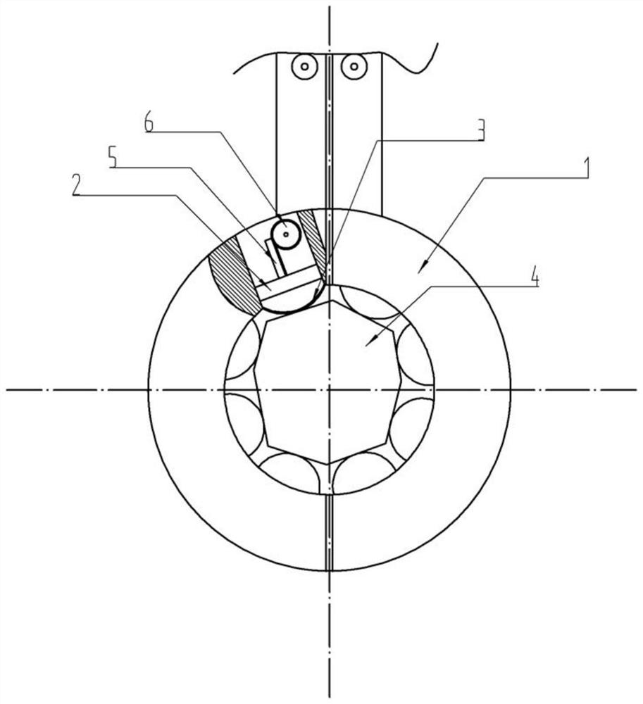
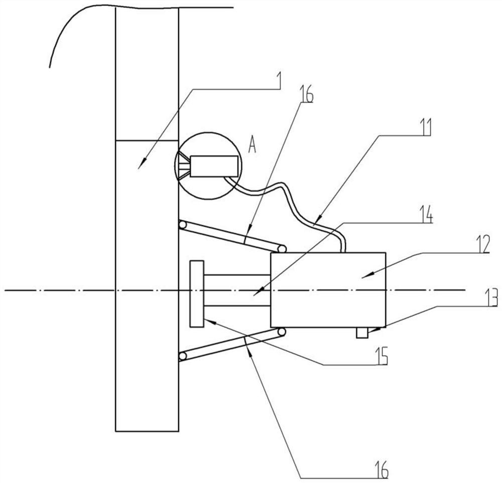
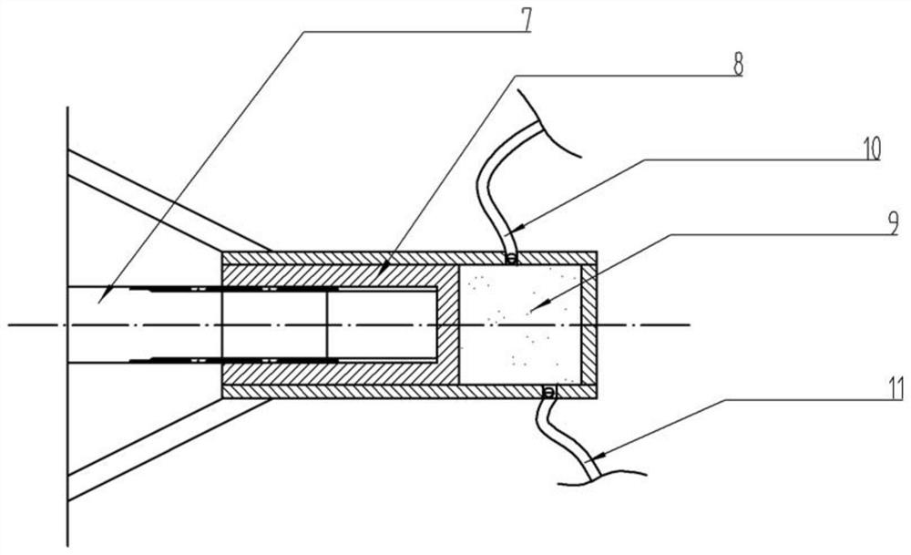
[0029] The reference signs in the drawings of the description include: clamp arm 1, piston 2, bottom 3, workpiece 4, rack 5, gear 6, rotating shaft 7, slider piston 8, liquid chamber 9, liquid inlet pipe 10, liquid outlet pipe 11. Telescopic hydraulic cylinder 12, liquid discharge valve 13, piston rod 14, push plate 15, telescopic rod 16.

[0030] The embodiment is basically as attached figure 1 Shown:

[0031] The industrial robot gripper includes a gripping part, which is ring-shaped and formed by combining two semi-circular gripping arms; it also includes a driving part that drives the opening and closing of the gripping part. The available form of the driving part is Many of them are in the prior art, so I won’t go into details here; there are a plurality of sliding chambers evenly distributed in the inner circumference of the clamp arm, and the bottom 3 of the sliding chamber ...


PUM


Abstract

This patent discloses a clamper for an industrial robot, which includes a clamping part, the clamping part is ring-shaped, and is formed by combining two semi-circular clamping arms; it also includes a driving part that drives the opening and closing of the clamping part; There are a plurality of sliding cavities evenly distributed in the inner circumference of the clamp arm, the bottom of the sliding cavity is on the inner peripheral wall of the clamping part, and the bottom is made of elastic material; The piston radially slides, and the piston forms an airtight air bag with the bottom, and the air bag is filled with air; the piston is provided with an electromagnet. The invention also discloses an industrial robot using the industrial robot gripper as an end effector, which overcomes the limitation that the existing industrial robot gripper has a limited gripping range and is dedicated to special objects, and has a wide gripping range and strong adaptability.

Description

technical field [0001] The invention relates to the technical field of industrial robots, in particular to an industrial robot gripper and an industrial robot. Background technique [0002] When the robot is performing operations, a certain device must be installed at the end of the robot's wrist. This assembly is used to directly complete the task. Jobs are successfully performed when the actions of such a device, known as an end effector, also known as a robotic gripper, are coordinated with the movements of the robot's wrist and arm. [0003] In the industrial robot system, the design of the end of the manipulator is very important to reduce the error and cycle time. Since this part is in direct contact with the physical environment, usually the working error can be attributed to many aspects, but the problem often occurs in the end fixture. A well-designed gripper at the end of the manipulator can greatly improve the efficiency, improve the reliability of the system, an...

Claims


Application Information

Patent Timeline
Patent Type & Authority Patents(China)
IPC IPC(8): B25J15/00B25J15/02
CPCB25J15/00B25J15/0023B25J15/0246
Inventor 陆世勇
Owner 宁波隆锐机械制造有限公司
Why Eureka
Try Eureka