Large-stroke oil gas suspension with rebounding device

A technology of oil-pneumatic suspension and large stroke, which is applied in the direction of elastic suspension, cantilever mounted on the pivot, suspension, etc., which can solve the problems of suspension cushioning characteristics, rapid rear swing of the wheel, and rapid drop of the wheel, etc., to achieve Increase durability, reduce friction area, and work stably and reliably

Inactive Publication Date: 2018-09-07
CHINA NORTH VEHICLE RES INST
View PDF6 Cites 2 Cited by
  • Summary
  • Abstract
  • Description
  • Claims
  • Application Information

AI Technical Summary

Problems solved by technology

During the use of the rocker suspension, because the rocker needs to swing at a large angle, the suspension stroke is generally much larger than that of the traditional suspension. When encountering large bumps on the ground or rocks, the rear suspension link is stretched rapidly: if

Method used


Image

  • Large-stroke oil gas suspension with rebounding device
  • Large-stroke oil gas suspension with rebounding device
  • Large-stroke oil gas suspension with rebounding device

Examples


example 1

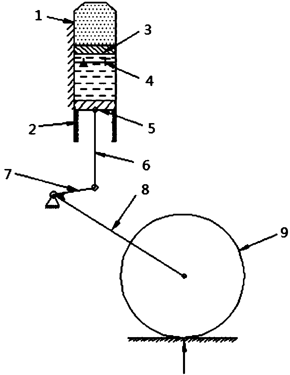
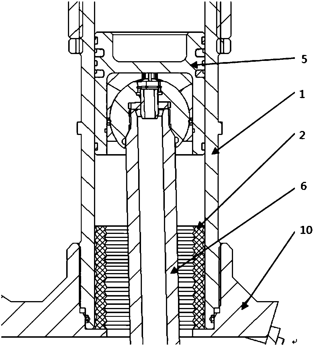
[0029] Such as figure 1 and Figure 5 As shown, the present invention provides a large-stroke oil-pneumatic suspension with a rebound device. When the vehicle equipped with the rocker suspension passes through the ground obstacle 11, the wheel 9 will move vertically along the fixed rotatable axis of the pull arm and the rocker 8 in an arc, and the pull arm 7 fixed with it will be connected with the pull arm 7 The connecting rod 6 connected in a hinged manner is pushed upward, and the movement of the connecting rod drives the main piston 5 in the fixed cylinder 1 fixed in the housing 10 to move upward; between the main piston 5 and the floating piston 3 is high-pressure oil And damping valve 4, the main piston 5 moves upward through the damping valve 4 to drive the floating piston 3 to move upward; because there is high-pressure gas between the floating piston 3 and the fixed cylinder 1, the gas is compressed, thus playing a buffering role. When the wheel passes through the o...

example 2

[0031] figure 2 It is the state diagram of the suspension when the rebound device does not work. When the unmanned vehicle crosses the vertical obstacle, the motion analysis diagram is as follows: Figure 4 As shown, the middle wheel is suspended in the air; when the wheel encounters a large bump or a stone on the ground, the motion analysis diagram is as follows Figure 5 As shown, the wheel encounters the backward acting force of the ground obstacle 11. In both cases, the connecting rod will quickly stretch out under the action of the high-pressure gas in the spring. At this time, the rebound device will play a role, effectively restrain the pull-down of the connecting rod, and make it rebound quickly. The working state diagram is as follows Figure 6 shown.

[0032] In the present invention, the bellows structure made of rubber is adopted, and the structure is simple, and the assembly and disassembly are convenient. If it needs to be replaced due to damage or reaching ...


PUM


Abstract

A large-stroke oil gas suspension with a rebounding device comprises a rocker arm installed on a wheel and a pulling arm arranged on the rocker arm, wherein a certain acute angle is formed between therocker arm and the pulling arm. The suspension is characterized in that the device comprises a fixing cylinder barrel, a floating piston, a damping valve, a main piston and a connecting rod, whereinthe floating piston, the damping valve, the main piston and the connecting rod are sequentially arranged in the fixing cylinder barrel; the rebounding device is arranged between the connecting rod andthe fixing cylinder barrel; the provided suspension suitable for the rocker arm is simple in structure and suitable for a large-cylinder-diameter rocker arm suspension device, work is stable and reliable, the connecting rod can be effectively restrained from being quickly pulled out and can rebound quickly, and the structure of the suspension is a corrugated pipe type structure; meanwhile, the friction area of rubber and the inner wall of the cylinder barrel can be reduced through the corrugated shape, friction is reduced, and durability is enhanced; and under the effect of the rebounding device, the connecting rod cannot be stretched quickly and can rebound quickly after being stretched.

Description

technical field [0001] The invention relates to the mechanical field, in particular to a large-stroke oil-pneumatic suspension with a rebound device. Background technique [0002] The rocker suspension is a suspension whose rocker can swing at a large angle. This suspension can play a great role in the driving and obstacle-crossing process of unmanned vehicles, which greatly improves the passage of unmanned vehicles on various road surfaces. sex. During the use of the rocker suspension, because the rocker needs to swing at a large angle, the suspension stroke is generally much larger than that of the traditional suspension. When encountering large bumps on the ground or rocks, the rear suspension link is stretched rapidly: if the wheels are suspended in the air, the wheels will drop rapidly; if the wheels encounter large bumps or rocks, the wheels will swing back quickly, The rocker arm is almost in a vertical position, and the cushioning characteristics of the suspension ...

Claims


Application Information

Patent Timeline
IPC IPC(8): B60G7/00B60G13/06
CPCB60G7/00B60G13/06B60G2202/24
Inventor 段国柱宋慧新侯友山陈宇王超肖洁
Owner CHINA NORTH VEHICLE RES INST
Why Eureka
Try Eureka