Material filling device

A filling device and material technology, applied in the pipeline system, mechanical equipment, gas/liquid distribution and storage, etc., can solve problems such as easy slippage of steel cylinders, difficulty in meeting demand, and burning of MO sources, so as to shorten working time and improve filling Improvement of filling efficiency and filling accuracy

Pending Publication Date: 2018-09-07
JIANGSU NATA OPTO ELECTRONICS MATERIAL
View PDF0 Cites 2 Cited by
  • Summary
  • Abstract
  • Description
  • Claims
  • Application Information

AI Technical Summary

Problems solved by technology

During the filling process, due to the extremely volatile characteristics of some types of MO sources, it is easy to fill the glove box with gaseous MO sources, which causes a large amount of adsorbates (such as organic solvent adsorption columns) in the glove box to be consumed , requiring frequent replacement
[0004] With the rapid development of the market economy and the increasing application of electronic technology, the market demand for MO sources has increased significantly, and the specifications of steel cylinders used for fill

Method used


Image

  • Material filling device

Examples


Example Embodiment

[0024] In order to have a clearer understanding of the technical features, purposes and effects of the present invention, specific implementations are now described in detail.

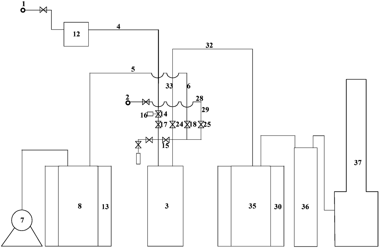
[0025] like figure 1 As shown, the material filling device includes a container 3 to be filled, a material delivery pipeline system, a vacuum pipeline system, an exhaust gas pipeline system and a nitrogen pipeline system, and the material delivery pipeline system connects the material source 1 and the container 3 Connected, the tail gas pipeline system, the vacuum pipeline system and the nitrogen pipeline system communicate with the material delivery pipeline system and the container 3;

[0026] The material delivery pipeline system includes a material delivery pipeline 4 and a first valve 14 arranged on the material delivery pipeline 4, the material inlet end of the material delivery pipeline 4 is connected to the material source 1, and the material of the material delivery pipeline 4 The outlet end ...


PUM


Abstract

The invention relates to a material filling device. The material filling device comprises a to-be-filled container, a material conveying pipeline system, a vacuum pipeline system, a tail gas pipelinesystem and a nitrogen pipeline system. A material source and the container are connected through the material conveying pipeline system. The tail gas pipeline system, the vacuum pipeline system and the nitrogen pipeline system communicates with the material conveying pipeline system and the container. The material conveying pipeline system comprises a material conveying pipeline and a first valvearranged on the material conveying pipeline. The material inlet end of the material conveying pipeline is connected to the material source. The material outlet end of the material conveying pipeline is connected to a material inlet of the container. A control device is connected with the first valve and controls opening and closing of the first valve. By adoption of the material filling device, material filling work can be conducted in an ordinary environment, a safe gas atmosphere is provided for material filling, and safe material filling is achieved; and limitations from auxiliary devices such as a glove box are avoided, and operation is convenient, fast and safe.

Description

technical field [0001] The invention relates to a material filling device, which belongs to the technical field of chemical equipment. Background technique [0002] MO sources are high-purity metal-organic compounds, which are support materials for epitaxial growth using metal-organic chemical vapor deposition (MOCVD), such as GaAs, GaN, InP, AlGaAs and other compound semiconductor ultra-thin film materials, which can be used to produce LED epitaxy Chips, HEMT devices, semiconductor lasers, solar cells, etc.; it is one of the key materials for the development of the optoelectronics industry, and is also an essential raw material for the production of high-brightness, ultra-high-brightness luminescent materials and large-scale integrated circuits. The MO source has very active chemical properties and is extremely sensitive to air and water vapor. It will spontaneously ignite instantly in the air, and explode violently when it meets water. Therefore, the filling of the MO sou...

Claims


Application Information

Patent Timeline
IPC IPC(8): F17D1/08F17D1/02F17D3/01F17D5/00
CPCF17D1/02F17D1/08F17D3/01F17D5/00
Inventor 蔡岩馨陆平汪浩郭威
Owner JIANGSU NATA OPTO ELECTRONICS MATERIAL
Why Eureka
Try Eureka