
Laser conduction device

A transmission device and laser technology, applied in the field of laser lighting, can solve the problems of poor assembly flexibility and high hardware manufacturing cost of laser integrated headlights, and achieve the effect of increasing the irradiation distance, enhancing the flexibility of assembly and modification, and uniform distribution of light spots

Pending Publication Date: 2018-09-07
海宁福斯特电器有限公司
View PDF0 Cites 0 Cited by
  • Summary
  • Abstract
  • Description
  • Claims
  • Application Information

AI Technical Summary

Problems solved by technology

[0004] The object of the present invention is to provide a laser transmission device to improve the problems of high hardware manufacturing cost and poor assembly flexibility of the above-mentioned laser integrated headlights

Method used


Image

  • Laser conduction device
  • Laser conduction device
  • Laser conduction device

Examples


no. 1 example

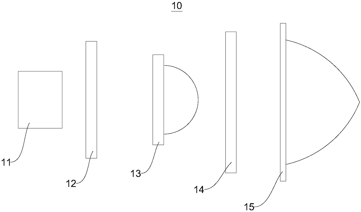
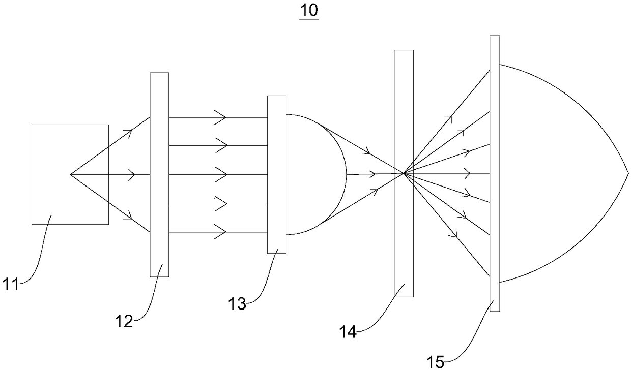
[0034] Please refer to figure 1 with figure 2 , figure 1 It is a schematic diagram of the assembly structure of a laser transmission device provided in the first embodiment of the present invention, figure 2 It is a schematic diagram of optical path transmission of a laser transmission device provided in the first embodiment of the present invention.

[0035] The laser transmission device 10 includes a laser light source 11 , a polygon mirror 12 , a focusing lens 13 , a fluorescence conversion device 14 and a beam shaper 15 .

[0036] As an embodiment, the laser light source 11, the polygon mirror 12, the focusing lens 13, the fluorescent conversion device 14 and the beam shaper 15 are all on the same straight line, so as to simplify the structure of the laser transmission device 10 and reduce the weight of the laser transmission device 10. volume.

[0037] The laser light source 11 is an electric light source that uses excited particles to emit light under the action of...

no. 2 example

[0051] The second embodiment of the present invention provides a constant current laser conduction device 20. The difference between the constant current laser conduction device 20 and the laser conduction device 10 provided in the first embodiment of the present invention is that in order to protect the fragile semiconductor laser array, To avoid damage to the semiconductor laser array caused by voltage fluctuations and temperature changes, the constant current laser transmission device 20 further includes a constant current laser controller 21 connected to the laser light source 11 .

[0052] Please refer to Figure 4 , Figure 4 It is a schematic diagram of the connection between a constant current laser controller and a laser light source provided by the second embodiment of the present invention.

[0053] The constant current laser controller 21 is connected to the laser light source 11 , and the power supply supplies power to the laser light source 11 under the control ...


PUM


Abstract

The invention provides a laser conduction device, and belongs to the technical field of laser illumination. The laser conduction device comprises a laser light source, a polygon prism, a focusing lens, a fluorescence conversion device and a beam shaper, wherein the optical centers of the polygon prism, the focusing lens, the fluorescence conversion device and the beam shaper are located on the same straight line, and a light beam output by the laser light source is incident on a focusing lens after passing through the multi-angle reflection of the polygon prism; the focusing lens focuses an adjusting light beam obtained through the multi-angle reflection is incident into the fluorescence conversion device so as to excite the fluorescence conversion device to generate an excitation light beam, and the excitation light beam is mixed with a focused light beam incident by the focusing lens to form a white light beam; and the white light beam is incident to the light beam shaper, the lightbeam shaper is used for shaping and adjusting the white light beam into a preset light spot and then uniformly emits the light spot. While the laser conduction and light spot forming are enabled to bemore accurate by the laser conduction device, each element is arranged in a straight line, so that the automobile lamp of the laser conduction device is smaller and compact in size, and installationand maintenance can be easily carried out.

Description

technical field [0001] The invention relates to the technical field of laser lighting, in particular to a laser transmission device. Background technique [0002] With the rapid development of the modern social economy, the number of cars in all countries in the world has increased rapidly. Among them, the growth rate of the number of cars in my country is almost above 10%. And sales are growing explosively. The increase in vehicles has brought greater pressure on traffic safety, and people are paying more and more attention to the quality and safety of vehicles. Vehicle headlights and other lighting devices play an important role in ensuring the driving safety of vehicles. Therefore, the headlight lighting system has also developed rapidly with the development of automobile technology. It only takes a few years from HID to LED, and the life of the car lights has changed from halogen lamps From 1000 hours to 5000 hours of LED lights, the power consumption is also reduced fr...

Claims


Application Information

Patent Timeline
Patent Type & Authority Applications(China)
IPC IPC(8): F21S41/16F21S41/20F21S41/25F21W107/10F21Y115/30
CPCF21S41/16F21S41/20F21S41/25F21Y2115/30F21W2107/10
Inventor 吴智平仝太朋
Owner 海宁福斯特电器有限公司
Learn More