
A textile high-efficiency humidifying device

A humidification device and high-efficiency technology, applied in the air humidification system, heating method, pipeline arrangement, etc., can solve the problems of small steam dissipation coverage, insufficient contact between water and heat source, slow evaporation rate, etc. , The effect of large humidification coverage and fast water evaporation rate

Active Publication Date: 2020-05-05
广州太行安全设备制造有限公司
View PDF7 Cites 0 Cited by
  • Summary
  • Abstract
  • Description
  • Claims
  • Application Information

AI Technical Summary

Problems solved by technology

[0003] In the existing textile workshop, it is necessary to maintain a certain air humidity to ensure the quality of spinning, but most of the existing spinning workshops are still carried out by sprinkling water on the ground or humidifying the air conditioner, and the humidification effect is poor. Some heating evaporation devices have insufficient contact between water and heat source, slow evaporation rate, poor effect, and small steam coverage area

Method used


Image

  • A textile high-efficiency humidifying device
  • A textile high-efficiency humidifying device
  • A textile high-efficiency humidifying device

Examples


Embodiment Construction

[0020] The technical solutions of the present invention will be further described in detail below in conjunction with specific embodiments.

[0021] In describing the present invention, it should be understood that the terms "center", "longitudinal", "transverse", "upper", "lower", "front", "rear", "left", "right", " The orientations or positional relationships indicated by "vertical", "horizontal", "top", "bottom", "inner", "outer", etc. are based on the orientation or positional relationships shown in the drawings, and are only for the convenience of describing the utility model and simplified descriptions, rather than indicating or implying that the device or element referred to must have a specific orientation, be constructed and operated in a specific orientation, and therefore should not be construed as limiting the invention. In addition, the terms "first", "second", etc. are used for descriptive purposes only, and should not be understood as indicating or implying rela...


PUM


Abstract

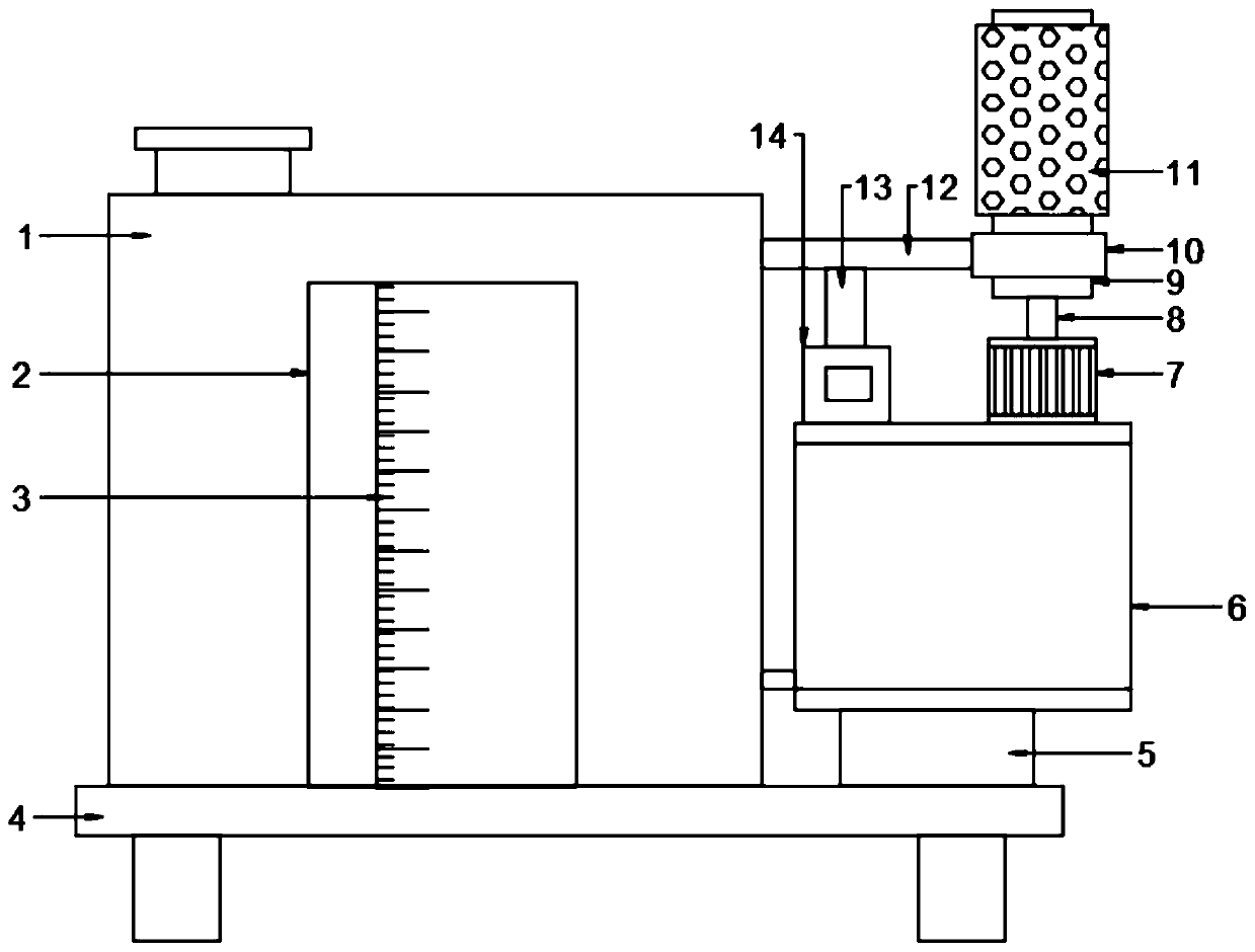
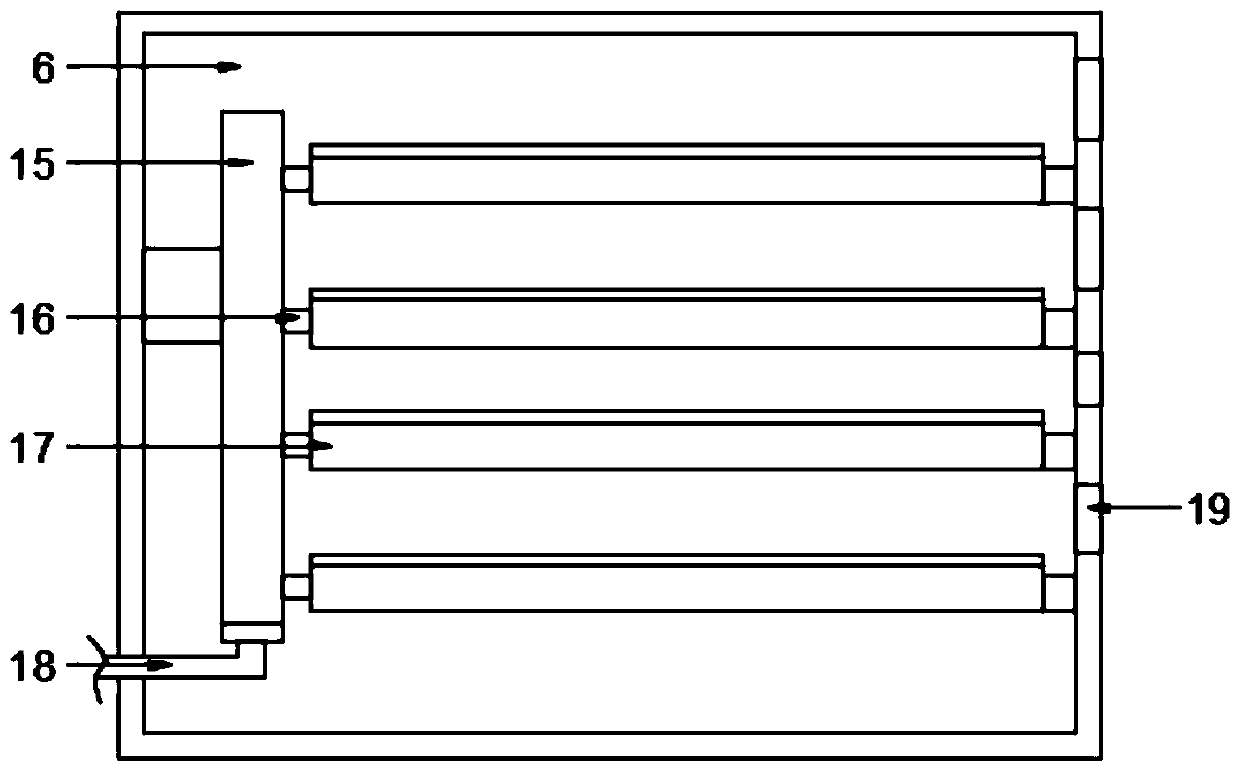
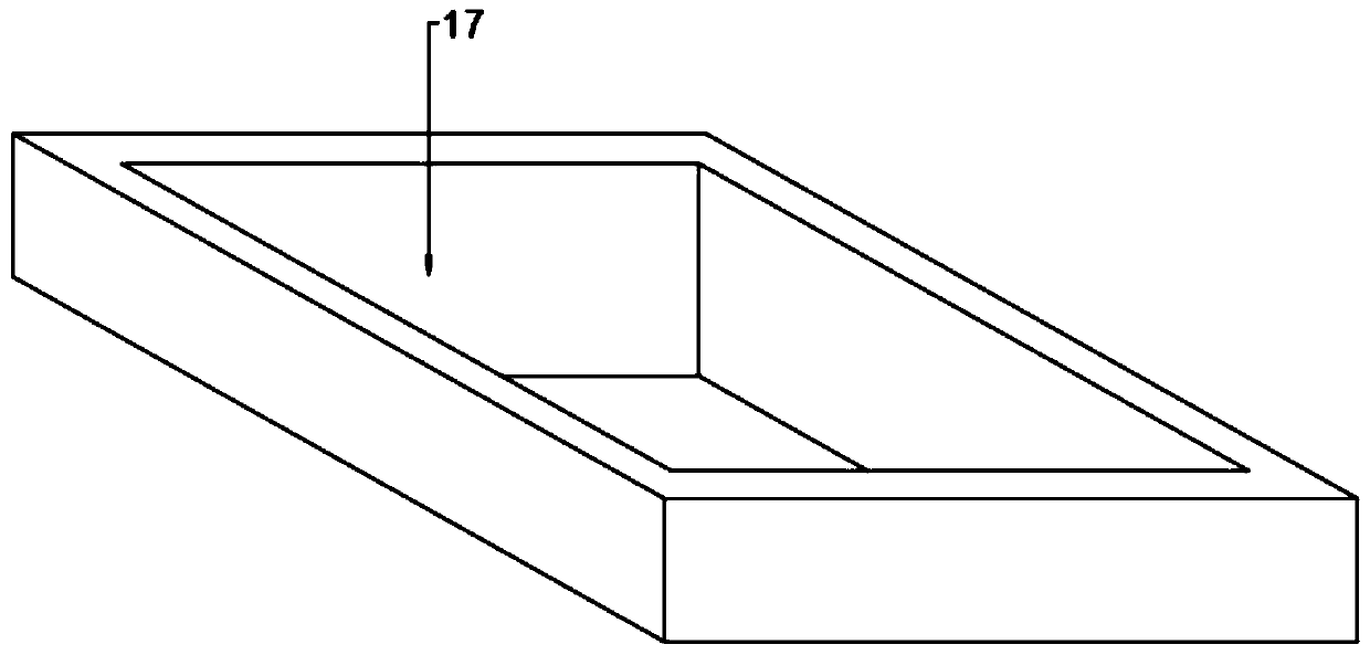
The invention discloses an efficient humidifying device for textile manufacturing. The efficient humidifying device comprises a water tank, an evaporation tank and a suction fan. The lower end of thewater tank is fixed to a bottom plate, and the lower end of the evaporation tank is fixed to the bottom plate through a supporting column. The suction fan is fixed to the upper end of the evaporationtank, the lower end of the suction fan communicates with the evaporation tank, and the upper end of the suction fan is provided with a connecting pipe. The upper end of the connecting pipe is connected to a fixed rod, a cavity is formed inside the fixed rod, the left end of the cavity communicates with the connecting pipe, and the right end of the cavity communicates into an air guiding tank. Theair guiding tank is fixed to the left end of the fixed rod and arranged on a rotary pipe in a sleeving mode. The rotary pipe communicates with the air guiding tank through a connector in the side wallof the rotary pipe, the upper end of the rotary pipe is sleeved with an air guiding sleeve, and the air guiding sleeve communicates with the rotary pipe through the connecting pipe. The lower end ofthe rotary pipe is fixed to a rotary shaft, and the lower end of the rotary shaft is fixed to an output shaft of a motor. According to the efficient humidifying device for textile manufacturing, the contact area of water and a heat source is large, the water evaporation rate is high, the water evaporation effect is good, thus the humidifying coverage range is large, the humidifying effect is good,and textile manufacturing is facilitated.

Description

technical field [0001] The invention relates to a humidifying device, in particular to a textile high-efficiency humidifying device. Background technique [0002] The original meaning of textile is taken from the general term of spinning and weaving, but with the continuous development and improvement of the textile knowledge system and subject system, especially after the emergence of non-woven textile materials and three-dimensional composite weaving technologies, the current textile is not only a traditional Hand spinning and weaving also include garment, industrial and decorative textiles produced by non-woven technology, modern three-dimensional weaving technology, and modern electrostatic nano-netting technology. Therefore, modern textile refers to a multi-scale structure processing technology of fibers or fiber aggregates. Ancient Chinese textile and printing and dyeing technology has a very long history. As early as the primitive society, the ancients knew how to ob...

Claims


Application Information

Patent Timeline
Patent Type & Authority Patents(China)
IPC IPC(8): F24F6/10F24F13/00F24F13/06
CPCF24F6/10F24F13/00F24F13/06F24F2013/0608
Inventor 何艺斓
Owner 广州太行安全设备制造有限公司
Learn More