
Optical coupling system and optical coupling method

An optical coupling and beam technology, applied in the field of optical coupling systems, can solve the problems of increasing the complexity and cost of the transceiver package, and the standard optical fiber is not suitable.

Active Publication Date: 2018-09-07
FOXCONN (KUNSHAN) COMPUTER CONNECTOR CO LTD +1
View PDF6 Cites 1 Cited by
  • Summary
  • Abstract
  • Description
  • Claims
  • Application Information

AI Technical Summary

Problems solved by technology

Use of angled fiber pigtails or fiber ferrules adds complexity and cost to the transceiver package
At the same time, these methods are not suitable for applications that require the use of standard optical fibers

Method used


Image

  • Optical coupling system and optical coupling method
  • Optical coupling system and optical coupling method
  • Optical coupling system and optical coupling method

Examples


Embodiment Construction

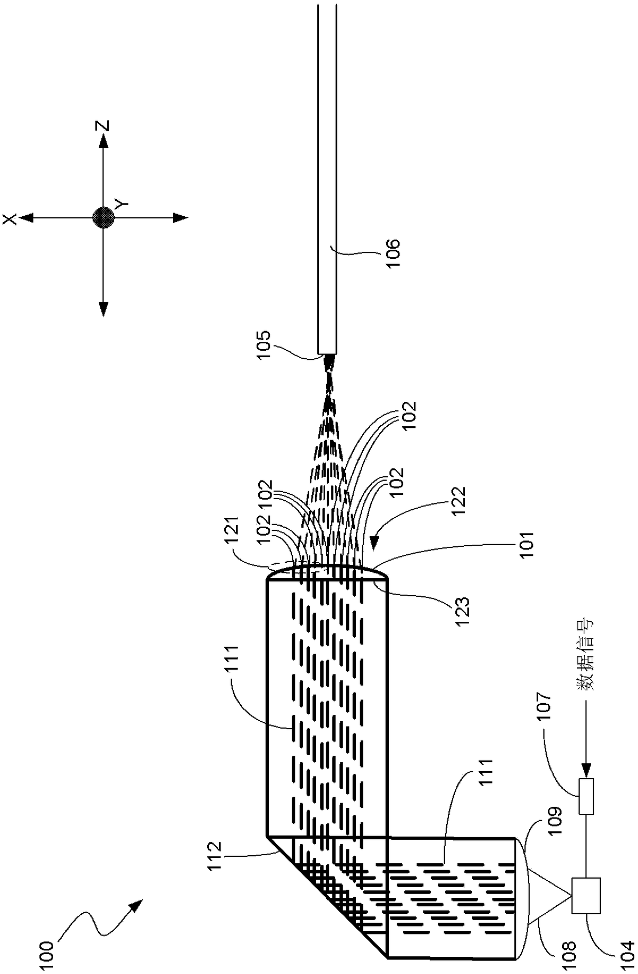
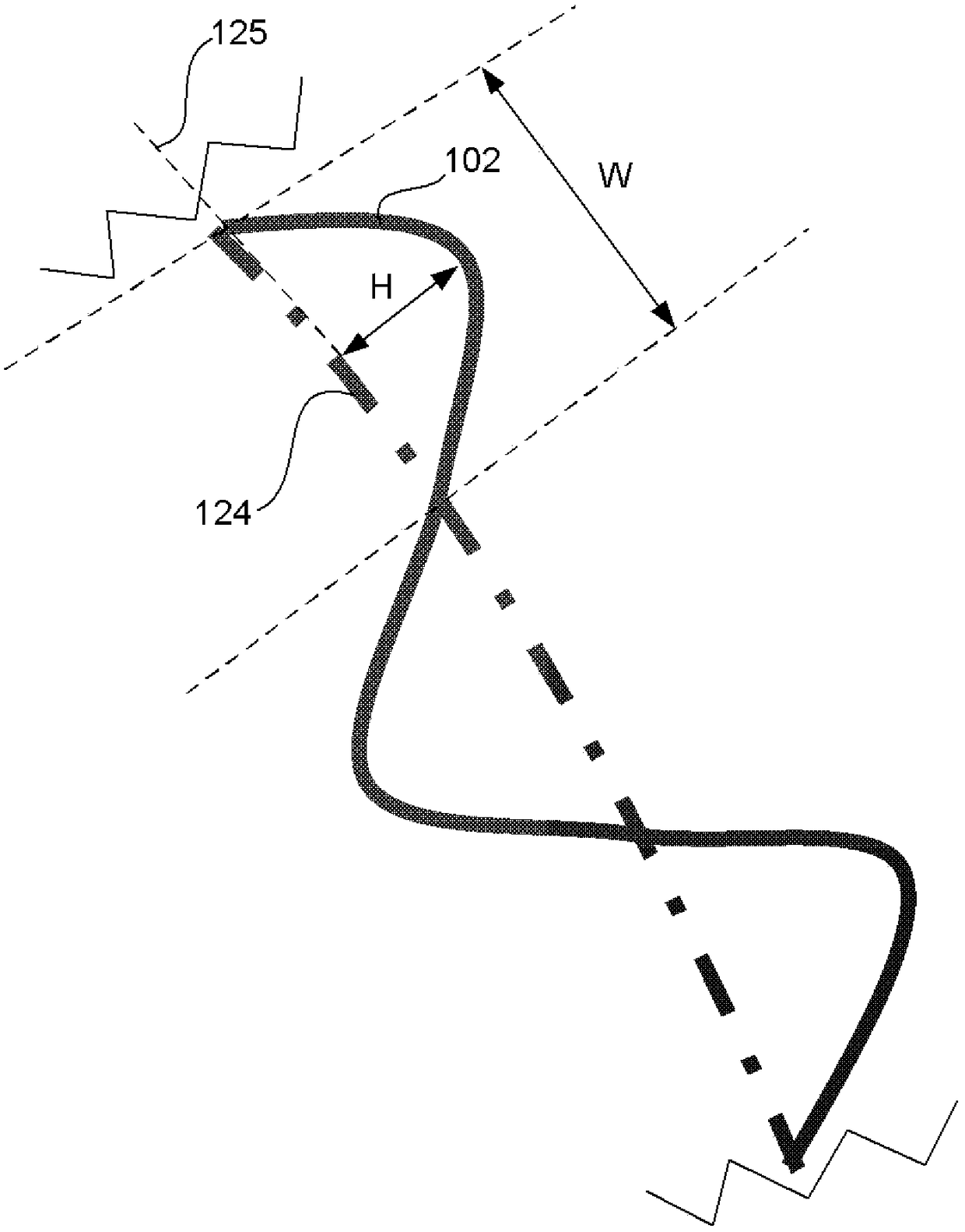
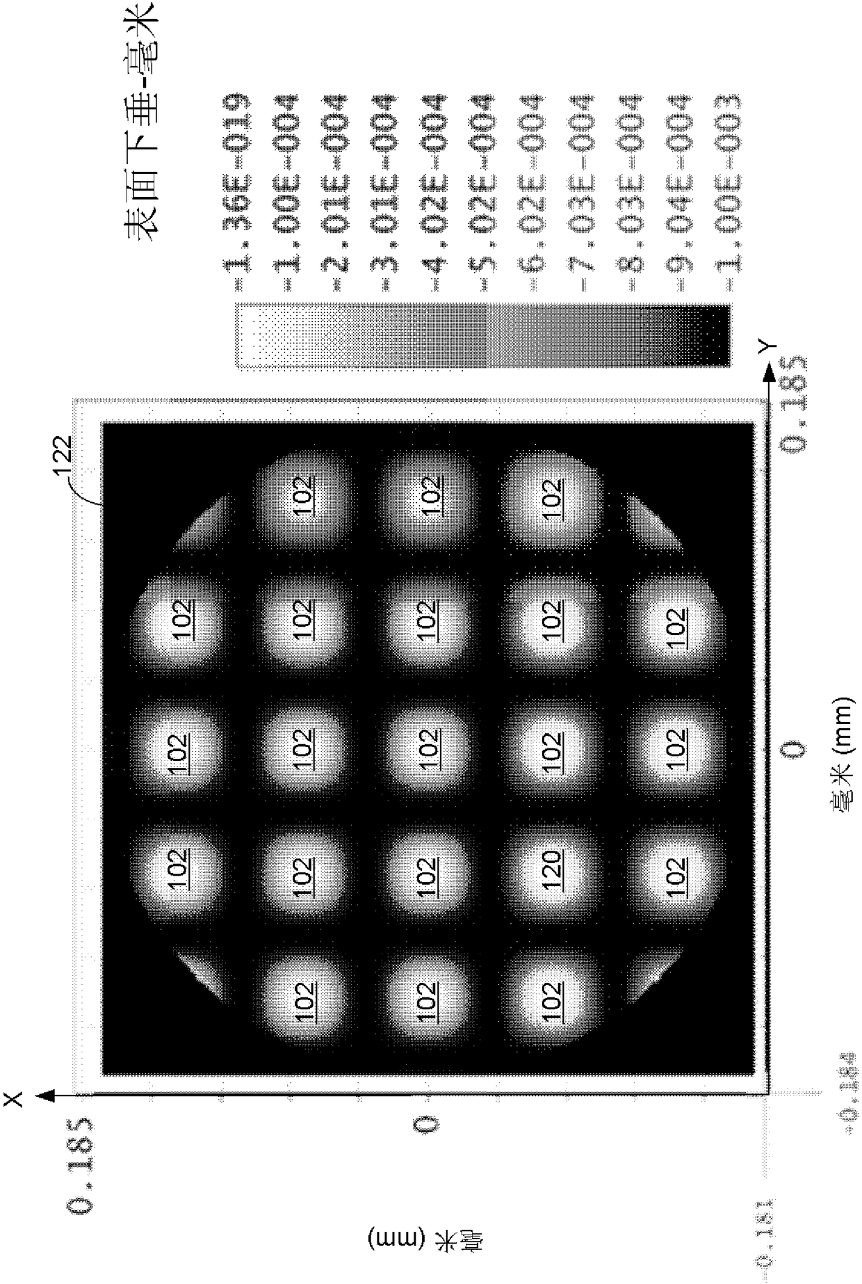
[0022] Consistent with representative or exemplary embodiments described herein, an optical coupling system and method for an optical communication module is provided to improve forward optical coupling efficiency through better mode matching and reduced back reflection. The optical coupling system includes at least one curved optical surface having a perturbation formed thereon, the optical surface having at least one portion such that the perturbation intersects an optical path of the curved optical surface. The shape, size and position of the perturbation changes the phase of the laser beam in a predetermined manner to control the emission of the laser beam to the end facet of the optical waveguide in a predetermined manner, improving mode matching and reducing back reflection. now refer to Figures 1 to 12 Embodiments are described illustratively or representatively, where like reference numerals represent like features, components, or elements.

[0023] In the following ...


PUM


Abstract

An optical coupling system is provided for coupling a light beam onto an end face of an optical waveguide in an optical communication module group. The optical coupling system comprises a curved optical surface positioned along an optical pathway of the optical coupling system and a plurality of perturbations disposed on an outer side of the curved optical surface. A light beam generated by a light source and propagating along an optical pathway of the optical coupling system in a first direction is incident on the curved optical surface having the perturbations formed therein. Each perturbation has a localized refractive effect on a portion of the light beam that is incident on the curved optical surface to form a respective light beam portion at a predetermined plane. The perturbations are shaped, sized and positioned such that a predetermined aggregated refractive effect of partially or fully overlapping all of the respective light beam portions at the predetermined plane forms a complex light beam shape at the predetermined plane that is different in shape from respective shapes of each of the respective light beam portions. The complex light beam shape is preselected to matcha spatial and an angular distribution of a plurality of light modes of the optical waveguide.

Description

【Technical field】 [0001] The present invention relates to an optical communication module, in particular to an optical coupling system for an optical communication module, the optical coupling system can reduce the back reflection of the beam emitted to the end face of the optical waveguide, and at the same time improve the beam mode and mode matching between the optical waveguide modes. 【Background technique】 [0002] In an optical communication network, optical communication modules, such as optical transceivers, transmitter and receiver modules, are used to transmit and receive optical signals between optical waveguides, usually optical fibers. The optical transceiver module includes a transmitting end and a receiving end. At the transmitting end, the laser light source emits laser beams, and the optical coupling system receives these laser beams and optically couples these laser beams to the end face of the optical fiber cable. The laser light source typically includes...

Claims


Application Information

Patent Timeline
Patent Type & Authority Applications(China)
IPC IPC(8): G02B6/42
CPCG02B6/4206G02B6/4255G02B6/4296G02B6/4207G02B6/4214G02B6/14G02B6/4208G02B6/32
Inventor 蒙塔汗.欧密德
Owner FOXCONN (KUNSHAN) COMPUTER CONNECTOR CO LTD
Learn More