Surface wiping machine for disc-shaped parts

A technology for parts and discs, which is applied in the field of disc-shaped parts surface wiping machines, can solve the problems of lower yield rate, affect the quality of cleaning, grinding and polishing, and high labor intensity, so as to avoid re-pollution and scratches and ensure the wiping effect And the effect of improving quality and processing efficiency

Pending Publication Date: 2018-09-11
SUZHOU JIANGJIN AUTOMATION TECH
2 Cites 4 Cited by

AI-Extracted Technical Summary

Problems solved by technology

[0002] For disc-shaped or ring-shaped parts, when processing or testing or surface cleaning or grinding or polishing, it is necessary to make the upper and lower surfaces of the parts face up to facilitate the corresponding operations. The existing operation is mainly to manually place the parts in a Wipe with a wiping machine after positioning, the efficiency of manual loading and unloading is low, the labor intensity is high, the automation of the whole process of loading, wiping, and unloading cannot be realized, and the integration of the equipment is poor
[0003] There are also some structures that use manipulators to load and unload parts. However, conventional two-jaw manipulators often move by clamping the upper and lower surfaces or the outer peripheral surface of the parts. Contacting and applying force can easily cause damage to the surface of the part, resulting in defective products and reducing the yield rate. Moreover, when the surface is cleaned or ground or polished, the jaws are also likely to cause re-contamination and damage to the surface ...

Method used

Preferably, as shown in accompanying drawing 5, described driving device 2 comprises cylinder 21, and the tail end of described cylinder 21 is pivotally connected on a base 22, and its piston rod 211 is pivotally connected to a One end of the adapter 23, the other end of the adapter 23 has a connection hole 231 perpendicular to its upper and lower surfaces in the extension direction, the opening area of ​​the connection hole 231 is adjustable, and the adjustment is mainly realized by the following structure: The position of the connecting hole 231 is provided with a notch 233 extending from its outer end surface 232 to the connecting hole 231, and coaxial through holes 234 are formed on the regions on both sides of the notch 233, through which bolts (not shown in the figure) shown) through the two through holes 234 and connected by nuts (not shown in the figure), the position of the nuts on the bolts is adjusted, so that the size of the notch 233 can be adjusted, thereby realizing the adjustment of the size of the connecting hole 231 .
Wherein, as shown in accompanying drawing 1, described parts placement groove 7 is the profiling structure that matches with workpiece shape, can make parts snap in wherein and make the surface to be wiped of parts protrude from described parts placement groove 7. The part placement groove 7 is set on the rotating device 20 that drives it to rotate around its central axis. The reason why it is set ...

Abstract

The invention discloses a surface wiping machine for disc-shaped parts. The surface wiping machine comprises a part storage tank, a part supply machine, a part recovery machine, a feeding and discharging robot and a wiping device, wherein the part storage tank is provided with a limiting groove used for storing parts; a plurality of to-be-wiped parts can be stacked on the part supply machine, andthe uppermost part is located at the to-be-clamped altitude; the part recovery machine is used for stacking multiple wiped parts; the feeding and discharging robot is provided with clamping jaws whichcan make contact with the outer circumferential surfaces of the parts and are matched with one another to clamp the parts, and can move between the part supply machine, the part storage tank and thepart recovery machine; and the wiping device is used for wiping a part placed on the part storage tank. According to the scheme, the independent stations can be organically combined through the feeding and discharging robot to form an automatic system, so that the automation degree is high, and the machining efficiency is improved; and meanwhile, the clamping jaws of the feeding and discharging robot make contact with the circumferential surfaces of the disc-shaped parts, so that damage to the upper and lower surfaces of the parts is avoided; and meanwhile, the problem that the parts are contaminated and scratched again after being wiped can be solved, and the wiping effect and quality of the parts can be guaranteed.

Application Domain

Grinding machinesGrinding work supports +1

Technology Topic

EngineeringAutomation +2

Image

  • Surface wiping machine for disc-shaped parts
  • Surface wiping machine for disc-shaped parts
  • Surface wiping machine for disc-shaped parts

Examples

  • Experimental program(1)

Example Embodiment

[0047] Objects, advantages and features of the present invention will be illustrated and explained by the following non-limiting description of preferred embodiments. These embodiments are only typical examples of applying the technical solutions of the present invention, and all technical solutions formed by adopting equivalent replacements or equivalent transformations fall within the protection scope of the present invention.
[0048]In the description of the scheme, it should be noted that the terms "center", "upper", "lower", "left", "right", "front", "rear", "vertical", "horizontal", " The orientation or positional relationship indicated by "inner", "outer", etc. is based on the orientation or positional relationship shown in the drawings, and is only for the convenience of description and simplification of description, rather than indicating or implying that the device or element referred to must have a specific orientation , constructed and operated in a particular orientation and therefore should not be construed as limiting the invention. In addition, the terms "first", "second", and "third" are used for descriptive purposes only, and should not be construed as indicating or implying relative importance. Moreover, in the description of the solution, with the operator as a reference, the direction close to the operator is the proximal end, and the direction away from the operator is the distal end.
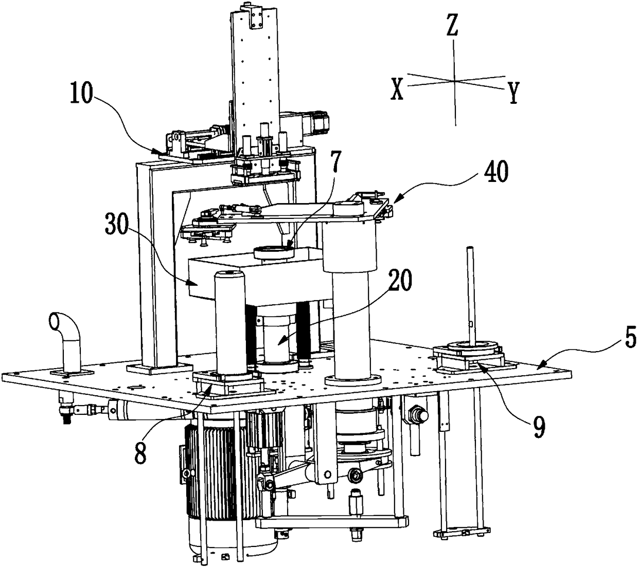
[0049] The disc-shaped part surface wiping machine disclosed by the present invention is described below in conjunction with the accompanying drawings, which includes a frame (not shown in the figure), and the frame has an opening and/or a structure of a door that can be opened and closed, and the door can pass through various locks. For locking, a base plate 5 is arranged in the cavity of the frame, as attached figure 1 As shown, the substrate 5 is provided with at least
[0050] Part placement slot 7 has a limiting slot for placing a part;
[0051] Parts supply machine 8, which can stack multiple parts to be wiped and make the top part at the height to be clamped;
[0052] Parts recycling machine 9 for stacking a plurality of wiped parts;
[0053] The loading and unloading robot 40 has at least one set of grippers 1 that can be in contact with the outer peripheral surface of the part and cooperate to realize the clamping of the part, which can transfer the parts at the height to be clamped on the part supply machine 8 to the part placement slot 7 And transfer the parts in the parts placement slot 7 to the parts recycling machine 9;
[0054] The wiping device 10 is used for wiping the surface of the disc parts on the parts placement groove 7 .
[0055] Among them, as attached figure 1 As shown, the part placement groove 7 is a profiling structure matched with the shape of the workpiece, which can make the parts snap into it and make the surface of the part to be wiped protrude from the part placement groove 7, and the part placement groove 7 is set On the rotary device 20 that drives it to rotate around its central axis, the reason why it is arranged on the rotary device 20 is to consider that the wiping disk of the wiping device 10 cannot completely cover the surface to be wiped of the entire part, and the surface of the part can be made Different areas of the wiper are in contact with the wiping disc to ensure coverage and uniformity of wiping.
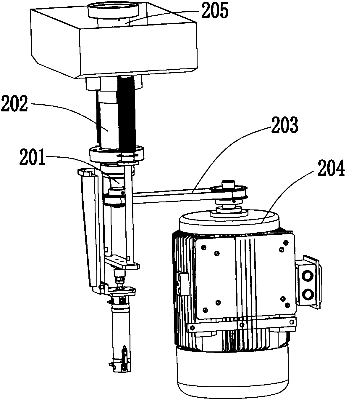
[0056] as attached figure 2 As shown, the rotating device 20 includes a support column 201, the support column 201 is inserted into a guide sleeve 202 vertically penetrating through the base plate 5 and fixed on the base plate 5, both ends of which are located outside the guide sleeve 202 and It can rotate relative to the guide sleeve 202. For example, the support column 201 is connected to the guide sleeve 202 through a bearing, or it can be in other forms. The lower end of the support column 201 is connected to the motor 204 that drives its rotation through a belt transmission structure 203. Of course, it can also be Gear transmission, crank connecting rod transmission and other structures are adopted, the top of the support column 201 is provided with the placement groove 7, and the top of the support column 201 is also provided with a protective cover 205 extending at least to the top of the guide sleeve 202 , the protective cover 205 shields the top opening of the guide sleeve 202, thereby effectively preventing the waste liquid from wiping from entering the guide sleeve 202 during the wiping process and causing corrosion and wear to the support column 201 and the bearing and other structures. .
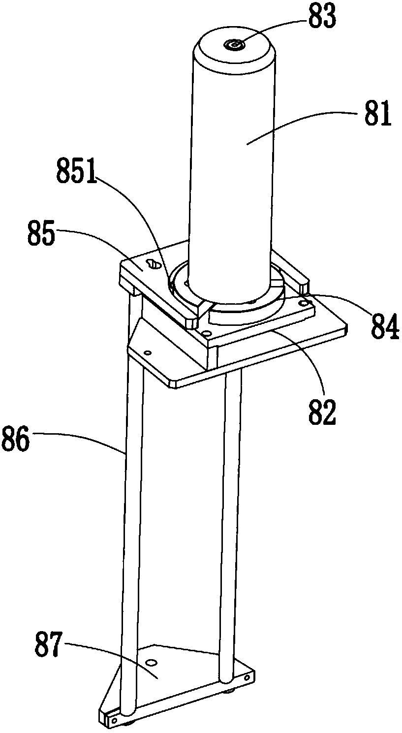
[0057] as attached image 3 As shown, the parts supply machine 8 includes a guide column 81 located above the base plate 5 and a lifting structure that drives the parts mounted on the guide column 81 to move to the top position of the guide column 81 one by one. Specifically, the guide column 81 is set on the outer periphery of a column 83 provided on a base 82, the column 83 is perpendicular to the base plate 5, and is coaxially connected to the disk 84 provided on the base 82, and the lifting mechanism includes a support plate 85, which has a semicircular notch 851 coaxial with the disc 831, which forms an arc-shaped slot with the disc 84, and the support disc 83 is set on the power device that drives it up and down. The power device includes at least one support shaft 86 located at the bottom of the support plate 85, the support shaft 86 is connected to the electric cylinder (not shown in the figure) through a connecting plate 87, and of course other strokes can be adjustable and can drive A device or structure that supports the vertical movement of the shaft 86, such as a stroke-adjustable oil cylinder, a structure composed of a motor+screw, or a structure composed of a motor+gear+rack, etc.
[0058] as attached figure 1 As shown, the structure of the parts recycling machine 9 and the parts supplying machine 8 is preferably the same, but of course they can also be different. The top of the column 81 is easy to grab by the loading and unloading robot, that is, when the top part is grabbed, the lifting device is activated to move the next part to the height to be clamped; and the part recovery machine 9 The support plate 85 is normally on the top of the guide column, and when receiving a wiped part, it moves down by a position, so that the parts on it move down as a whole until the guide column can no longer place parts.
[0059] Since the surface of the workpiece needs to be wiped, the loading and unloading robot 40 needs to avoid contact with the upper and lower surfaces of the parts when loading and unloading. Correspondingly, as attached Figure 4 As shown, the loading and unloading robot 40 includes two screw-on manipulators 6, and each of the screw-on manipulators 6 can be used for clamping various disc-shaped, sheet-shaped or plate-shaped or ring-shaped parts, especially Applicable to disc parts or ring parts or parts with disc parts, as attached Figure 5 , attached Image 6 As shown, it includes at least three jaws 1 distributed in a polygonal shape, and several jaws 1 can each rotate forward or reverse synchronously around a longitudinally extending axis, where the longitudinally extending axis refers to the axis parallel to the central axis of the part Axes, Axes that extend horizontally are those that are perpendicular to the central axis of the part.
[0060] When rotating forward, the end opening formed by several jaws 1 expands or shrinks,
[0061] When reversing, the change trend of the end opening formed by several jaws 1 is opposite to that during forward rotation;
[0062] The combined end opening of several jaws 1 is larger than the outer circumference of the object to be clamped when it is the largest, and smaller than the outer circumference of the object to be clamped when the combined end opening of several jaws 1 is the smallest.
[0063] Specifically, as attached Figure 5 As shown, the jaw 1 includes a frustum-shaped main body 11 with a small top and a large bottom, or a main body with a concave curved surface. The radius of the bottom surface of the limiting platform 12 is greater than the radius of the bottom surface of the truncated conical main body 11, so that when clamping, it can effectively prevent the disc-shaped parts from falling off from several jaws 1. A connecting shaft 13 for connecting other components.
[0064] as attached Figure 5 , attached Image 6 As shown, the number of jaws 1 is preferably three and distributed in an equilateral triangle, and they are driven to rotate by the same driving device 2. Of course, in other embodiments, each jaw 1 may also be driven by its own driving device.
[0065] preferred, as attached Figure 5 As shown, the driving device 2 includes a cylinder 21, the tail end of the cylinder 21 is pivotally connected to a base 22, and its piston rod 211 is pivotally connected to one end of an adapter 23 through a connecting rod. The other end of the connector 23 has a connection hole 231 perpendicular to its upper and lower surfaces in the extension direction. The opening area of ​​the connection hole 231 is adjustable. The adjustment is mainly realized by the following structure: a slave Its outer end surface 232 extends to the notch 233 at the connecting hole 231, and coaxial through holes 234 are formed on the regions on both sides of the notch 233, through which two through holes are penetrated by bolts (not shown in the figure). 234 and connected by a nut (not shown in the figure), the position of the nut on the bolt is adjusted, so that the size of the notch 233 can be adjusted, thereby realizing the adjustment of the size of the connecting hole 231.
[0066] as attached Figure 5 As shown, a rotating shaft 24 perpendicular to it and driven to rotate around the central axis is inserted into the connecting hole 231, and the upper end of the rotating shaft 24 is fixed in the connecting hole 231 by the above-mentioned bolts and nuts. The rotating shaft 24 is rotatably connected to a fixed support member 25, for example, it is connected to the support member 25 through various bearings, and the rotating shaft 24 runs through the support member 25, and the rotating shaft 24 is located at the end of the support member 25. The lower end bolt connects the central position of a divergent transmission member 26, as attached figure 2 As shown, the divergent transmission member 26 includes three branches 261 extending from the center to the outside with the same length, the angle between adjacent branches 261 is 120°, and each branch 261 of the divergent transmission member 26 is connected to a One end of the 7"-shaped connector 27, the other end of the connector 27 is connected to the connecting shaft 13 of a jaw 1, and the bending position of the connector 27 is rotatably arranged on the shaft on the support 25 251 , the shaft 251 is perpendicular to the bottom surface of the support member 251 and is connected to the through hole at the bending position of the connecting member 27 through a bearing (not shown in the figure).
[0067] In detail, as attached Image 6 As shown, a waist-shaped hole 262 is formed near the free end of each branch 261. The extension direction of the waist-shaped hole 262 is the same as the extension direction of the branch 261 where it is located. The short length of each connecting piece 27 is The outer end of the branch 273 is provided with a column 271 that can be embedded in the waist hole 262, and the roller 272 that fits the inner wall of the waist hole 262 is rotatably fitted on the column 271. The outer end of the long branch 274 of the member 27 is provided with the clamping jaw 1 , and the central axis of the clamping jaw 1 is parallel to the rotating shaft 24 .
[0068] And, the area of ​​the equilateral triangle formed with the outer ends of the short branches 273 of the three connectors 27 as vertices is always smaller than the equilateral triangle formed with the outer ends of the long branches 274 of the three connectors 27 as vertices. area.
[0069] Under normal conditions, the piston rod 211 of the cylinder 21 is in a contracted state, and the three jaws 1 are in a contracted state; when it needs to be opened, the piston rod 211 is stretched out, thereby pushing the rotating shaft 24 counterclockwise through the adapter 23 Rotate, the rotation of the rotating shaft 24 drives the divergent transmission part 26 to rotate counterclockwise, and then the three connecting parts 27 rotate counterclockwise synchronously, so that the three jaws expand outward synchronously to open; when clamping is required, the The piston rod 211 is retracted, the components move in reverse, and the jaws shrink.
[0070] The two screw-type manipulators are arranged on two vertical and equal-length mounting plates of a mounting frame 4, and the said screw-type manipulators 6 are driven by the moving device 3 to move to the part placement slot 7 and the part supply machine. 8 will grab and move the parts at the corresponding positions. Preferably, the moving device 3 can drive the mounting frame 4 to rotate 45° clockwise and 45° counterclockwise, so that two screw-type manipulators 6 at one position After grabbing one part respectively, the loading and unloading operation can be realized simultaneously in one rotation process, which is beneficial to improve the efficiency of loading and unloading.
[0071] The moving device 3 can be of various feasible structures, such as a six-axis robot or a structure composed of multiple electric cylinders capable of at least three-axis movement of XYZ, etc., which are known technologies here and will not be repeated here.
[0072] In a preferred embodiment, the moving device 3 includes a jacking and rotating mechanism that drives the screwing manipulator 6 to lift and rotate, and the jacking and rotating mechanism uses a lever principle to drive the screwing manipulator to go up and down.
[0073] For details, see attached Figure 7As shown, the jacking and rotating mechanism includes a bracket 31, and the bracket 31 includes two vertical plates arranged with gaps, which are bolted to the bottom of a base plate 5, and the lower end of the bracket 31 is pivotally connected to a transmission member 32, The transmission member 32 is Y-shaped as a whole, and one end of the transmission member 32 is pivotally connected to the piston rod 331 of the telescopic cylinder 33, and is driven by the telescopic cylinder 33 to rotate around the shaft 311 connected to the support 31. The V-shaped end of the piece 32 is movably connected to a fixed disk 34 .
[0074] as attached Figure 8 As shown, the two forked front ends of the V-shaped end are respectively provided with fixed shafts 321, and the fixed shafts 321 are rotatably provided with turntables or wheels or bearings 322, and the two turntables 322 are oppositely arranged and rotatable. embedded in the groove 341 at the outer peripheral surface of the fixed disk 34, specifically, the peripheral surface of the turntable or wheel or bearing 322 fits with the upper and lower inner surfaces of the groove 341, so the transmission member 32 can Rotating up and down relative to the fixed disk 34 , the fixed disk 34 can rotate around its central axis relative to the rotating disk 322 .
[0075] The fixed plate 34 is provided with a coaxial support shaft 35 passing through it, the support shaft 35 passes through the base plate 5 and is rotatably inserted into a sleeve 36 fixed on the base plate 5 and is controlled by the Sleeve 36 guides, and one end of the support shaft 35 located on the base plate 5 is connected with a mounting cap for connecting the mounting bracket, and the mounting cap extends to the upper end of the sleeve 36 and maintains a gap with the sleeve 36 , the fixed disk 34 is connected to a rotating device 37 that drives it to rotate around its central axis.
[0076] as attached Figure 8 As shown, the rotating device 37 is driven by a two-way cylinder or two driving cylinders 371 with piston rods assembled back to back, preferably driven by two driving cylinders 371 with piston rods assembled back to back, one of which drives the piston rod of the cylinder 371 to pivot Connect a fixed seat 372 fixed on the bottom of the base plate 5, one end of the piston rod of the other drive cylinder 371 is pivotally connected, and the other end of the transmission rod 373 is connected with the outer ring of the bearing 374 on the sleeve 36 , the outer ring of the sleeve bearing 374 is provided with at least one guide rod 375 parallel to the support shaft 35 and penetrating through the fixed disk 34. There are two guide rods 375, which equally divide the outer circumference of the bearing 374 , and they can move up and down relative to the fixed plate 34.
[0077] During loading and unloading work, when parts need to be grasped, the piston rod 331 of the telescopic cylinder 33 stretches out, driving the transmission member 32 to rotate counterclockwise around the shaft 311 connected to the bracket 31, and the V of the transmission member 32 The shaped end moves up so that the fixed plate 34 is lifted to a high position. After the fixed plate 34 is lifted, the support shaft 35 connected to it is driven to move upward relative to the sleeve 36, so that the manipulator on it moves to a high position. , one of the two drive cylinders 371 moves (the piston rod stretches or extends), and the action of the drive cylinder 371 drives the outer ring of the bearing 374 on the sleeve 36 to rotate through the transmission rod 373, thereby passing through two guides Rod 375 drives described fixed disc 34 to rotate, and then makes described support shaft 35 rotate, and makes the screw-on type manipulator on it rotate and move to the top of disc-shaped or ring-shaped workpiece, and then the piston rod of telescopic cylinder reversely moves to make the The screw-on manipulator moves down so that the workpiece is located in the space enclosed by the three jaws 1, and then according to the working process of the screw-on manipulator, the jaws shrink to achieve clamping and can be transported.
[0078] as attached Figure 9 As shown, the wiping device 10 includes a wiping plate 101, and the wiping plate 101 is arranged on a displacement mechanism that drives it to move in the X-axis and Z-axis directions. The displacement mechanism includes a gantry 102, and the gantry The top of the frame 102 is provided with at least one guide rail 103 extending along the X-axis direction, and a first slide plate 104 is slidably arranged on the guide rail 103, and the first slide plate 104 is connected to drive it to slide back and forth along the guide rail 103. The movable nut of leading screw 105, described leading screw is connected motor 106, and its movable nut 1051 and leading screw fixing seat are also respectively connected with a telescopic cover 107 that is sleeved on the outside of the screw rod of described cylinder, and described telescopic cover 107 can be in place The movable nut is telescopic when moving; the first sliding plate 104 is also provided with a mounting plate 108 disposed therewith, and the mounting plate 108 is provided with a guide 109 extending along the Z-axis direction, and the guide 109 can be A second slide plate 1010 is slidably provided, and the second slide plate 1010 is connected and fixed on the mounting plate 108 and can drive a cylinder 1020 that moves up and down along the guide member 109; the lower end of the second slide plate is provided with a L shaped mounting plate 1030, the L-shaped mounting plate 1030 is provided with a telescopic cylinder 1040 along the Z-axis direction, the piston rod of the cylinder 1040 is connected to the wiping disc 101, and the two sides of the cylinder 1040 are respectively provided with The guide rod 1050 vertically connected to the wiping plate 101 is inserted into the guide tube 1060 on the L-shaped mounting plate 1030 so as to move up and down. The rod 1050 is coaxial with the protective sleeve 1070 , the L-shaped mounting plate 1030 and the wiping plate 101 are respectively connected with a telescopic protective cover 1080 set on the outer periphery of the guide rod 1050 .
[0079] Of course, in other embodiments, the displacement mechanism can also be other feasible devices or structures, such as a six-axis robot or a structure capable of realizing XYZ three-axis movement, which is a known technology and will not be described in detail here; at the same time, the The wiping disc 101 can be a wiping sponge or a tensioned wiping cloth with a cleaning function or a grinding disc, a sand disc, a polishing disc, etc. with a grinding, polishing or surface treatment function, which are specifically set according to functional needs, preferably and in the present invention The wiping disc has cleaning and grinding functions, and cutting fluid is used to cooperate with the wiping disc for grinding during the wiping process. The structure of the equipment supplying cutting fluid is not shown in the figure.
[0080] Further, due to the existence of cutting fluid, waste liquid will be generated during the wiping process. If these waste liquids are not recovered, they will have an adverse effect on the operation of various components. Therefore, the above-mentioned various telescopic covers are also used to place waste liquids. Adverse effects on the corresponding shaft or component, corresponding, if attached figure 1 As shown, the disc-shaped part surface wiping machine also includes a waste liquid recovery device 30, and the waste liquid recovery device includes a collection tank 301. Under normal conditions, the opening of the collection tank 301 is located below the part placement tank 7, and the wiper , the opening of the collection tank 301 is located above the part placement tank 7 .
[0081] During specific implementation, its structure is as follows, as attached Figure 10 As shown, the collection groove 301 is coaxially set on the outer periphery of the guide sleeve 202, and the diameter of the central through hole 3011 is smaller than the diameter of the part placement groove 7, and the outer periphery of the central through hole 3011 is also provided with a secondary The inner bottom surface of the collection tank 301 extends vertically with a retaining ring 3012 of a certain height, and the bottom of the collection tank 301 is also provided with a through hole 3013, and the through hole is connected to a collection tank or a drainage structure or a waste liquid treatment structure through a pipeline. .
[0082] The collection tank 301 is also connected to a lifting device that drives it to lift, as attached Figure 10 As shown, the lifting device includes a jacking cylinder 303 fixed on a support frame 302, the support frame is fixed on the bottom of the base plate 5, and the jacking cylinder 303 is connected to two cylinders along the Z axis through an adapter plate 304. The two telescopic columns 305 are located on both sides of the guide sleeve 202 and can move up and down along the guides 306 on the substrate 5. The telescopic columns The end of 305 is connected to the bottom plate of the collection tank 301 through a seal 307, and the seal 307 and the guide 306 are respectively connected to one end of a telescopic cover 308, and the telescopic cover 308 is sleeved on the outer periphery of the telescopic cover 305 to It protects.
[0083] Finally, during the operation of the entire equipment, the extension and retraction of each cylinder, the start and stop of the motor, the forward and reverse rotation, the start and stop of other electrical equipment, and the switching of working states can be controlled by the signals of various sensors combined with software programming. , preferably controlled by various sensors (some sensors are hidden in the figure) combined with a PLC control system (not shown in the figure), for example, as shown in the attached Figure 4 As shown, when the telescopic cylinder 33 is controlled, it is controlled by the trigger block 38 at the end of the support shaft 35 and the proximity sensor 39 provided with a gap below it. Proximity sensor 376 and trigger block 377 are controlled, and described trigger block 377 is fixed on the described transmission rod 373, and two proximity sensors 376 are arranged on both sides of described trigger block 377 with equal gap; Figure 10 As shown, the sensors 1090 on both sides of the wiping block 101 are used to determine whether there are parts in the part placement groove 7 .
[0084] When the whole set of equipment is in operation, a set of parts set on the guide column 81 is stacked on the support plate 85 of the parts supply machine 8, wherein the topmost part is located at the uppermost position to be grabbed of the guide column 81, The supporting plate on the described parts recovery machine 9 is at the highest position.
[0085] At this time, the loading and unloading robot 40 drives the screw-on manipulator on the left side to rotate above the guide column 81 of the parts supply machine 8 and makes the equilateral triangle formed by the three jaws coaxial with the guide column 81, Then the screw-type manipulator 6 moves down and grabs the disc-shaped parts, then, the screw-type manipulator 6 rises and reversely rotates to the top of the part placement groove 7 and then descends to place the clamped parts In the part placement tank 7; then, the lifting cylinder 303 of the lifting device of the waste liquid recovery device 30 is activated to move the notch of the collection tank 301 to the top of the part placement tank 7.
[0086] The piston rod of the cylinder 1020 and/or cylinder 1040 of the wiping device 10 stretches out to make the wiping disc 101 contact the upper surface of the part. At this time, the motor 106 drives the wiping disc 101 to move back and forth, and the The motor 204 in the rotating device 20 is started to drive the parts placement tank 7 to rotate, and, during the wiping process, cutting fluid is added between the wiping disk 101 and the surface of the parts.
[0087] After wiping for a period of time, each motor stops working, and each cylinder acts in reverse. At this time, the two screw-on manipulators 6 are respectively positioned above the parts supply machine 8 and above the parts placement groove 7. The tightening manipulator 6 descends synchronously, so that the unwiped parts on the parts supply machine 8 and the wiped parts on the part placement groove 7 can be clamped at the same time, and then the two tightening manipulators 6 rise and rotate synchronously 45 ° and then descending, at this time, the parts that have not been wiped are located in the part placement groove 7, and the parts that have been wiped are located on the guide column of the part recovery machine 9, and the two screw-type manipulators rotate in the opposite direction after completion 45° reset.
[0088] The present invention still has various implementation modes, for example, a structure for exhausting or ventilating is provided on the equipment, so as to provide protection or vacuumize the environment in the frame, and all technologies formed by equivalent transformation or equivalent transformation schemes, all fall within the protection scope of the present invention.

PUM

no PUM

Description & Claims & Application Information

We can also present the details of the Description, Claims and Application information to help users get a comprehensive understanding of the technical details of the patent, such as background art, summary of invention, brief description of drawings, description of embodiments, and other original content. On the other hand, users can also determine the specific scope of protection of the technology through the list of claims; as well as understand the changes in the life cycle of the technology with the presentation of the patent timeline. Login to view more.

Similar technology patents

Foldable gliding frame and foldable scooter

Owner:苏州速蝶科技有限公司

High-precision fully-automatic cutting device and method thereof

Owner:昆山新井田智能设备有限公司

Wet garbage treatment device and wet garbage treatment method

Owner:环川环保设备(苏州)有限公司

Battery core stacking clamp

Owner:SUZHOU JEE INTELLIGENT EQUIP CO LTD

Classification and recommendation of technical efficacy words

  • Simple structure
  • exquisite design

Sharing system for air-conditioning coat

InactiveCN107440179ASimple structureeasy to wear
Owner:QINGDAO HAIER AIR CONDITIONER GENERAL CORP LTD

Feeding device of sorter of batteries plate

InactiveCN101357717ASimple structurecooperate well
Owner:NANJING NORMAL UNIVERSITY

Emergency parachuting device and method for multiple-rotor unmanned aerial vehicle

InactiveCN103895870Aavoid aircraft crashSimple structure
Owner:SOUTH CHINA AGRI UNIV +1

Intelligent luminous cup

InactiveCN103126456Aeasy to useexquisite design
Owner:TAIZHOU QIBANG IND DESIGN

Temperature difference energy driven ocean section movement system

InactiveCN105952691AIncrease the frequency of exerciseexquisite design
Owner:ZHEJIANG UNIV
Why Eureka
Try Eureka