Integrated paper pulp molding equipment and method

A pulp molding and molding equipment technology, applied in textiles and papermaking, etc., can solve the problems of affecting quality, pulp molding rupture and damage, wet embryo deformation, etc., so as to improve product quality and production efficiency, reduce industrial accidents, and improve densification. sexual effect

Pending Publication Date: 2018-09-11
重庆凯成科技有限公司
View PDF0 Cites 9 Cited by
  • Summary
  • Abstract
  • Description
  • Claims
  • Application Information

AI Technical Summary

Problems solved by technology

Pulp molding equipment in the prior art mostly uses manual demoulding. The wet embryo is manually removed and placed on a wet embryo rack, then transported to a drying room or air-dried under natural light, and then shaped to form a finished product. The mold is easy to deform the wet embryo and affect the quality
In addition, the pulp molding process in the prior art adopts single-side pulp

Method used


Image

  • Integrated paper pulp molding equipment and method
  • Integrated paper pulp molding equipment and method
  • Integrated paper pulp molding equipment and method

Examples


Embodiment 1

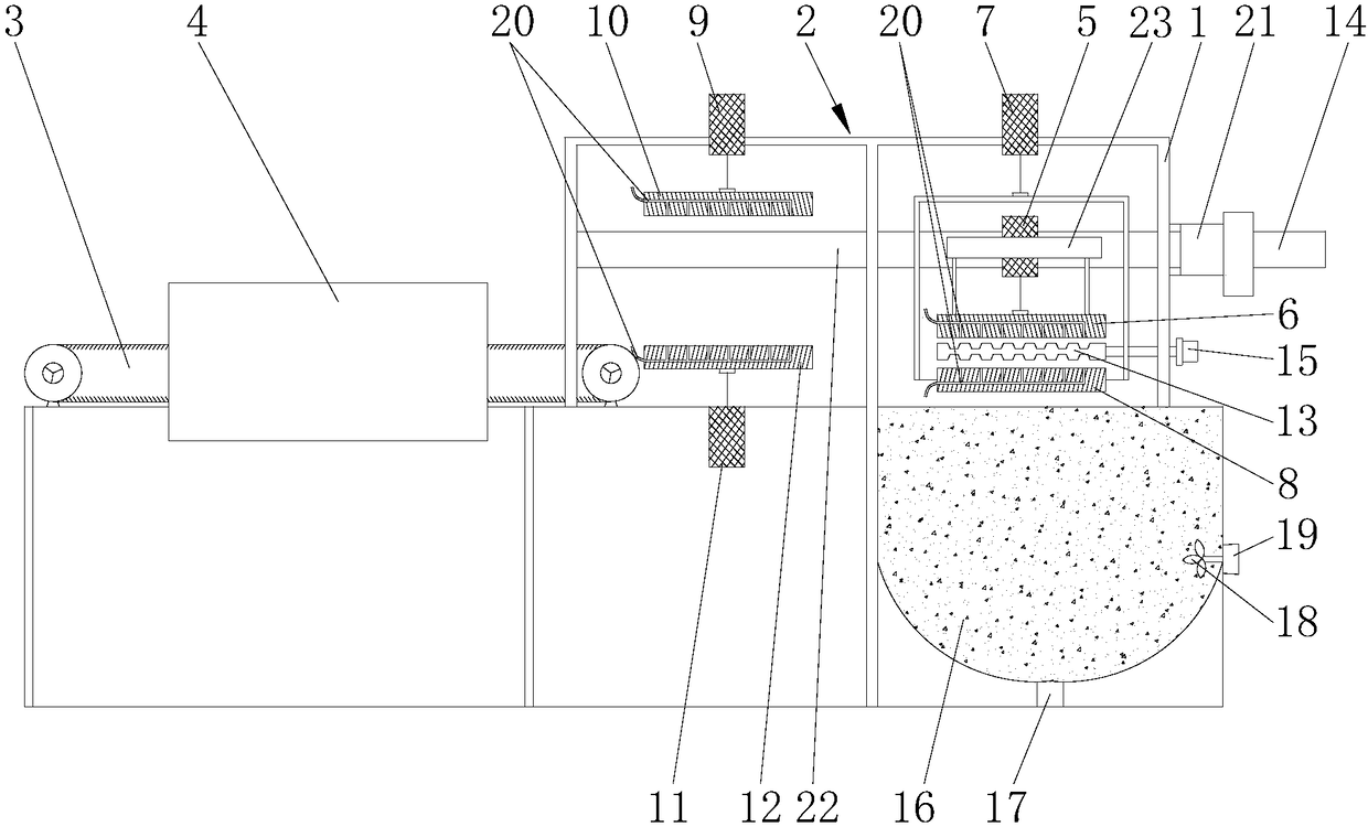
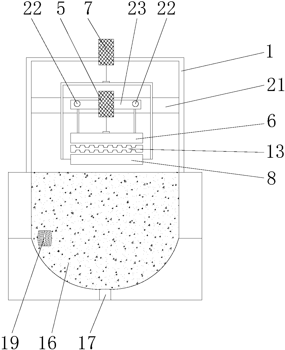
[0033] Embodiment 1 of the present invention: as Figure 1-Figure 3As shown, the integrated pulp molding equipment includes a frame 1, a molding mechanism 2, a conveying device 3, a drying mechanism 4 and a slurry tank 16, and the molding mechanism 2, conveying device 3 and drying mechanism 4 are all arranged on the frame 1, the conveying equipment 3 and the drying mechanism 4 are located on one side of the molding mechanism 2, the conveying equipment 3 is partly located in the drying mechanism 4, and the slurry pool 16 is located in the mold The bottom of molding mechanism 2. From the molding of the pulp in the molding mechanism 2 to the conveying equipment 3, the conveying equipment 3 is transported to the drying mechanism 4 for drying, which eliminates the process of manual handling in the prior art and reduces manpower. Ensure normal production, improve production efficiency, and make integrated preparation and drying possible. Integrated pulp molding equipment, the mold...

Embodiment 2

[0035] Embodiment 2: as Figure 1-Figure 3 As shown, the integrated pulp molding equipment includes a frame 1, a molding mechanism 2, a conveying device 3, a drying mechanism 4 and a slurry tank 16, and the molding mechanism 2, conveying device 3 and drying mechanism 4 are all arranged on the frame 1, the conveying equipment 3 and the drying mechanism 4 are located on one side of the molding mechanism 2, the conveying equipment 3 is partly located in the drying mechanism 4, and the slurry pool 16 is located in the mold The bottom of molding mechanism 2. From the molding of the pulp in the molding mechanism 2 to the conveying equipment 3, the conveying equipment 3 is transported to the drying mechanism 4 for drying, which eliminates the process of manual handling in the prior art and reduces manpower. Ensure normal production, improve production efficiency, and make integrated preparation and drying possible. The lower half of the slurry pool 16 is a hemisphere, the bottom of...

Embodiment 3

[0036] Embodiment 3: as Figure 1-Figure 3 As shown, the integrated pulp molding method adopts the above-mentioned integrated pulp molding equipment, including the following steps:

[0037] S1, after beating in the pulping workshop, the slurry is transported to the slurry pool 16 through the inlet and outlet port 17;

[0038] S2, the first horizontal driving device 14 drives the slurry suction upper mold support 23 to move along the guide rail 22, and then drives the slurry suction upper mold 6 to move to a position opposite to the slurry suction lower mold 8;

[0039] S3, the first lifting device 5 drives the slurry suction upper mold 6 down to the slurry pool 16, and the second lifting device 7 drives the slurry suction lower mold 8 down to the slurry pool 16, and the slurry suction upper mold 6 and the slurry suction lower mold 8 is covered with slurry, the first lifting device 5 drives the slurry suction upper mold 6 to rise, and the second lifting device 7 drives the slu...


PUM


Abstract

The invention relates to integrated paper pulp molding equipment, in particular to integrated paper pulp molding equipment and method. The integrated paper pulp molding equipment comprises a rack (1),a molding mechanism (2), delivery equipment (3), a drying mechanism (4) and a slurry pool (16), wherein the molding mechanism (2), the delivery equipment (3) and the drying mechanism (4) are all arranged on the rack (1), the delivery equipment (3) and the drying mechanism (4) are located at one side of the molding mechanism (2), the delivery equipment (3) is partially located in the drying mechanism (4), and the slurry pool (16) is located below the molding mechanism (2). Through a designed pulp absorbing mode, the paper pulp molding product thickness is increased, industrial accidents can bereduced, and the product quality and the production efficiency can be improved. The invention further provides an integrated paper pulp molding method. A top-bottom two-sided slurry absorbing mode isadopted, and the product compactness is improved.

Description

technical field [0001] The invention relates to a pulp molding equipment, in particular to an integrated pulp molding equipment and method. Background technique [0002] Paper and plastic products have a wide range of applications. Pulp molding equipment is mainly used to produce paper and plastic products, such as paper trays for eggs, paper trays for hand and red wine, and trays for electronic accessories. Pulp molding equipment in the prior art mostly uses manual demoulding. The wet embryo is manually removed and placed on a wet embryo rack, then transported to a drying room or air-dried under natural light, and then shaped to form a finished product. The mold is easy to deform the wet embryo and affect the quality. In addition, the pulp molding process in the prior art adopts single-side pulp suction, and the thickness of the pulp molded product is limited. If the pulp is simply continuously sucked to increase the thickness, it will cause problems such as poor compactne...

Claims


Application Information

Patent Timeline
IPC IPC(8): D21J5/00
CPCD21J5/00
Inventor 彭钢连盛张蓉梁志成
Owner 重庆凯成科技有限公司
Why Eureka
Try Eureka