Random-direction dynamic vector uniform magnetic field generating device and control system
A technology of dynamic vector and uniform magnetic field, applied in measuring devices, electromagnetic circuit devices, measuring magnetic variables, etc., can solve the urgent needs of difficult to meet the uniformity, time-varying, directivity and high precision of magnetic field control, poor dynamic performance, The direction of the application range is uncontrollable, etc., to achieve the effects of good stability, high magnetic field accuracy and convenient use
- Summary
- Abstract
- Description
- Claims
- Application Information
AI Technical Summary
Problems solved by technology
Method used
Image
Examples
Embodiment 1
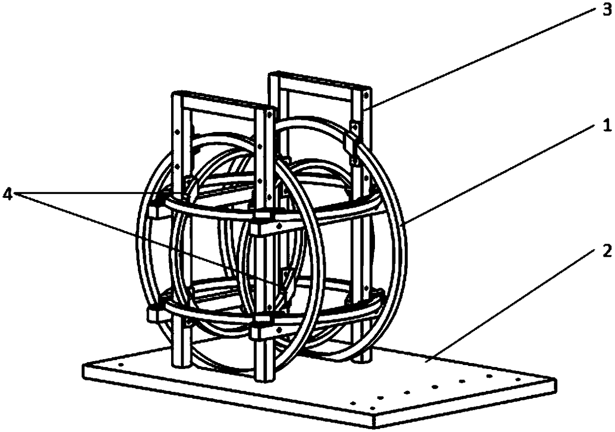
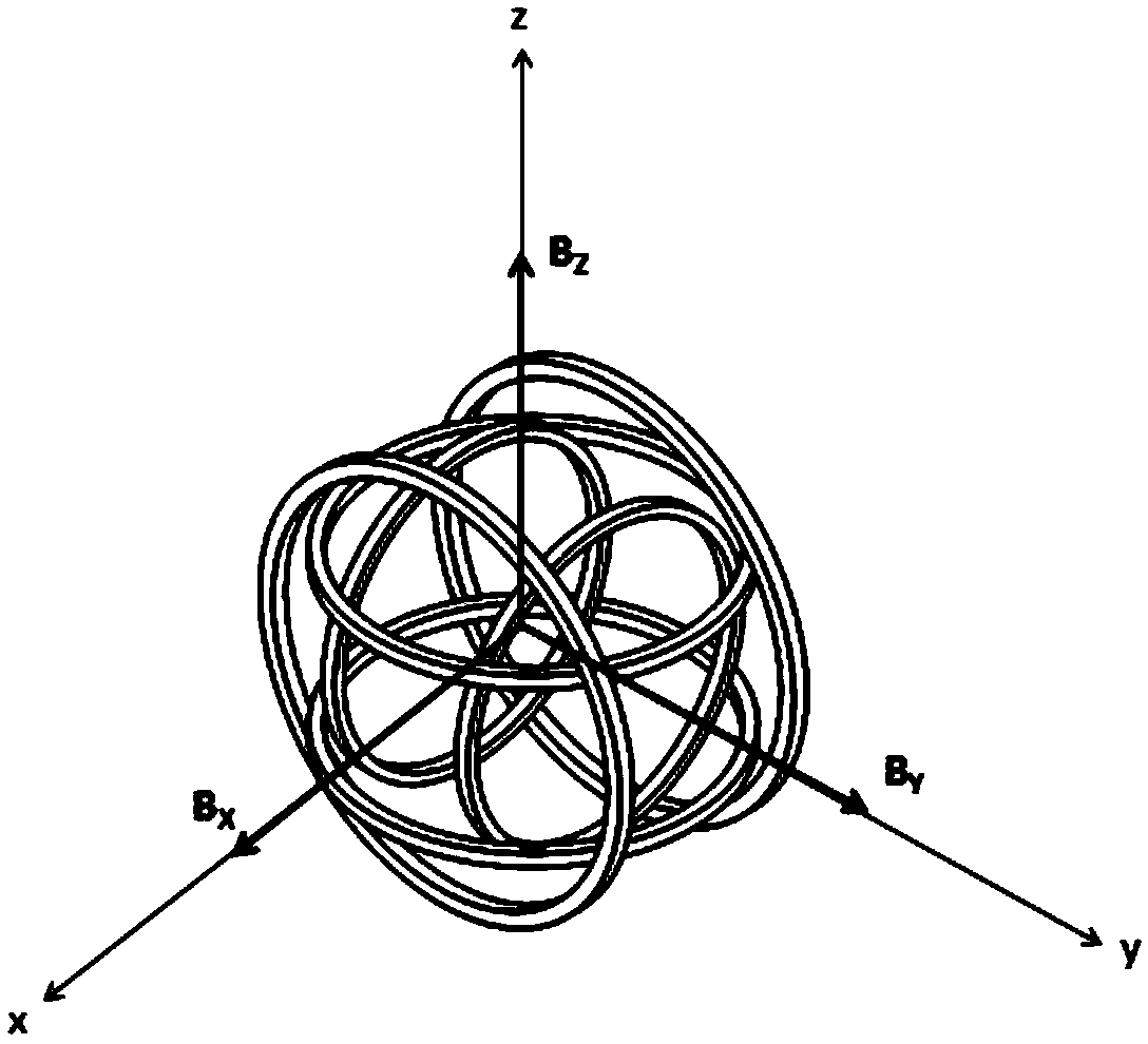
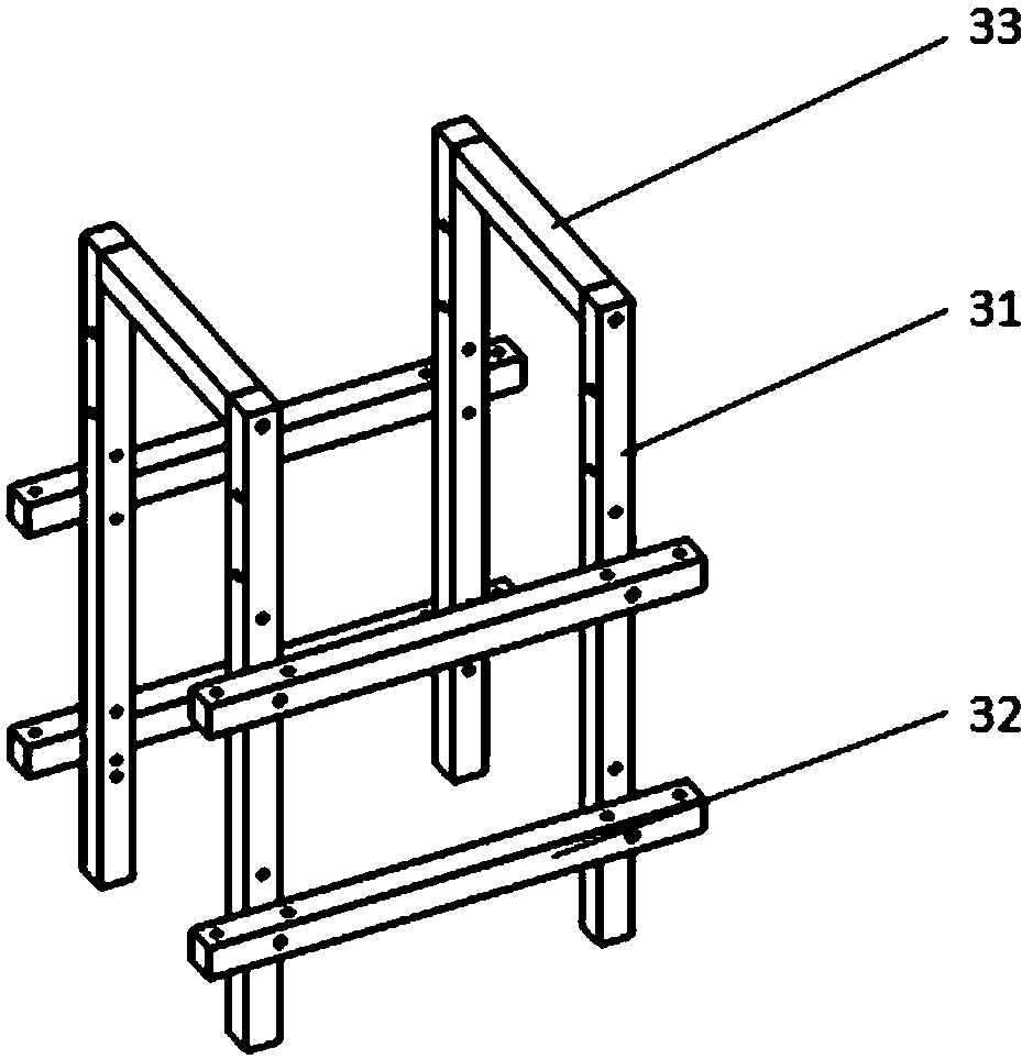
[0037] Such as figure 1 As shown in -6, the device for generating a dynamic vector uniform magnetic field in any direction provided by Embodiment 1 of the present invention includes; three sets of orthogonally placed Helmholtz coils 1, non-magnetic non-magnetic structural components and three-channel current sources; three sets The Helmholtz coils 1 are respectively wound around the X-axis, Y-axis, and Z-axis of the space coordinate system; each group of Helmholtz coils 1 includes two enamelled copper coils coaxially wound clockwise in series, The axial spacing of two enamelled copper coils in the same group is equal to the radius of the enamelled copper coils. The symmetry plane of each group of Helmholtz coils 1 is placed in a two-two orthogonal relationship with the geometric center of the device as the origin; the three-channel current source has three current output channels, which are independent from the X-axis, Y-axis, and Z-axis. Electrical connections that do not in...
Embodiment 2
[0076] Such asfigure 1 As shown in -6, Embodiment 2 of the present invention also provides a control system for a dynamic vector uniform magnetic field generator in any direction, including: a control device and the dynamic vector uniform magnetic field generator in any direction provided in Embodiment 1.
[0077] In an optional solution of this embodiment, the control device can realize circuit-independent and time-synchronized current output program control. Thus, a dynamic vector uniform magnetic field in any direction with controllable size, waveform and timing is generated.
[0078] In the optional scheme of this embodiment, such as Figure 6 As shown, the control device 6 includes a computer 61, a single-chip microcomputer 62, a chip 63 and a voltage-current conversion amplifier 64. The computer is electrically connected with the single-chip microcomputer, the single-chip computer is electrically connected with the chip, and the chip is electrically connected with the v...
Embodiment 3
[0081] Circular Helmertz coils belong to the magnetic field analysis of axisymmetric coils. In order to reduce the workload during calculation, the following assumptions should generally be followed:
[0082] 1. The coils are coaxially wound and distributed symmetrically in the center;
[0083] 2. The turns are evenly wound, the current section is uniform, and the current direction is in a right-handed spiral relationship with the symmetry axis;
[0084] 3. The turns are insulated, and the spacing is infinitely close, and all the turns fill the space occupied by the coil.
[0085] Such as figure 2 As shown, for any coaxial circular Helmertz coil, the calculation of the magnetic field at the central axis is required. Therefore, take the center point P(0,0,0), set the distance between the two coils as d, the radii are both R and coaxial, and take the midpoint of the line connecting the centers of the two coils as x=0, you can get:
[0086]
[0087] When d=R, the magnetic ...
PUM
 Abstract
Description
Claims
Application Information
 - R&D
- Intellectual Property
- Life Sciences
- Materials
- Tech Scout
- Unparalleled Data Quality
- Higher Quality Content
- 60% Fewer Hallucinations
Browse by: Latest US Patents, China's latest patents, Technical Efficacy Thesaurus, Application Domain, Technology Topic, Popular Technical Reports.
© 2025 PatSnap. All rights reserved.Legal|Privacy policy|Modern Slavery Act Transparency Statement|Sitemap|About US| Contact US: help@patsnap.com


