
Bone cement type interbody fusion cage and operation method thereof

A bone cement and fusion device technology, applied in the field of intervertebral fusion devices, can solve the problems of non-growth, operation failure, easy invagination and loosening, etc.

Pending Publication Date: 2018-09-18
唐朝阳
View PDF0 Cites 3 Cited by
  • Summary
  • Abstract
  • Description
  • Claims
  • Application Information

AI Technical Summary

Problems solved by technology

However, both autologous bone and allogeneic bone need to be implanted, and bone growth is required after implantation into the intervertebral space. If the amount of implanted bone is insufficient, the fixation is not firm, infection and other factors cause the implanted bone to not heal and not grow into the bone.
The intervertebral fusion cage will become loose, which will further cause the internal fixation to bear a large stress for a long time and cause fatigue fracture, which will lead to the failure of the operation.
Requires revision surgery, causing great pain to the patient
Moreover, for older patients with osteoporosis to implant intervertebral fusion devices, because osteoporosis cannot be embedded tightly, and it is easy to invaginate and loosen, and the operation method of direct bone grafting requires a longer bed rest time, about 3-6 months

Method used


Image

  • Bone cement type interbody fusion cage and operation method thereof
  • Bone cement type interbody fusion cage and operation method thereof
  • Bone cement type interbody fusion cage and operation method thereof

Examples


Embodiment 1

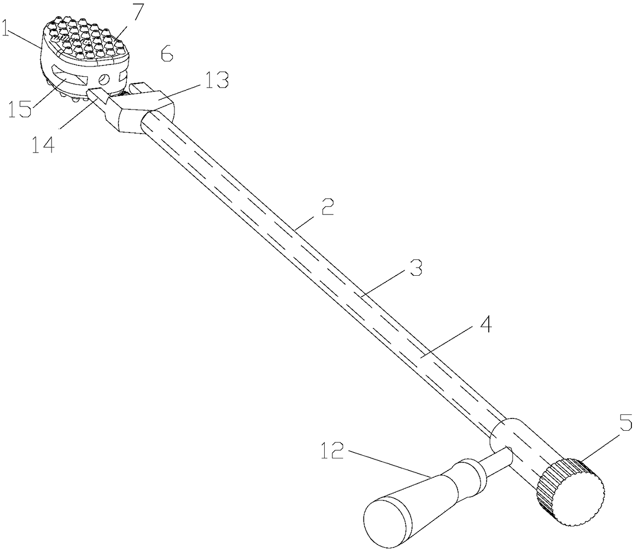
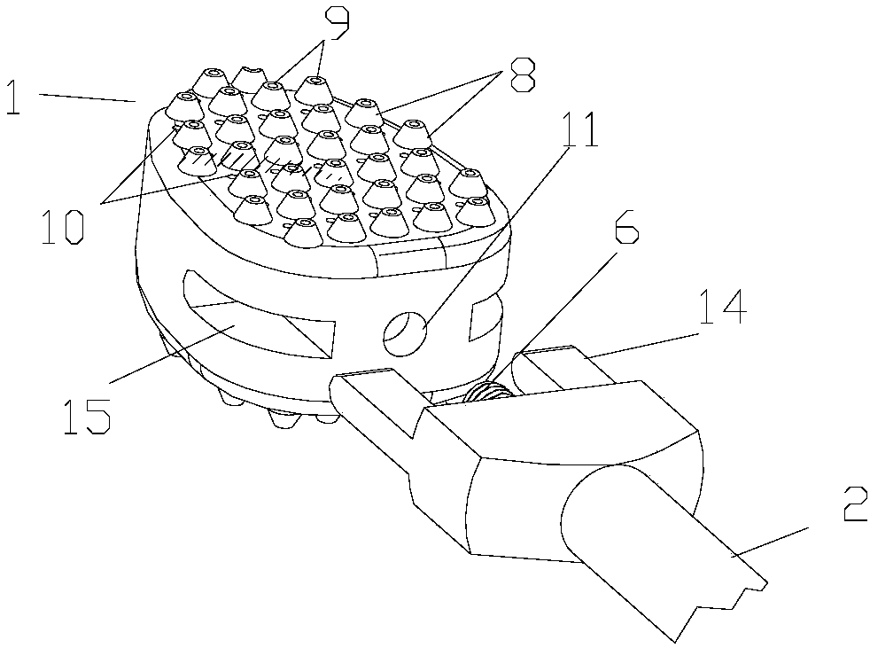
[0028] refer to figure 1 , 2 , this embodiment includes a bone cement fusion device 1, an injection rod 2, and a mounting screw 3. The injection rod is provided with an injection through hole 4, one end of which is open, and the other end is provided with a positioning protrusion. The injection through hole is coaxial and connected to the inner hole; one end of the installation screw 3 is provided with an end cap 5, and the other end is a threaded head 6, and the installation screw 3 passes through the injection through hole 4 of the injection rod 2, and its threaded head is the same as the bone cement type. The cage 1 is threadedly connected; the bone cement cage 1 is provided with a cavity, and has upper and lower two working surfaces 7, and the working surface 7 is provided with a plurality of raised spikes 8, and the spikes 8 are provided with long The through hole 9 and the working surface are provided with a short through hole 10, the long through hole 9 and the short t...

Embodiment 2

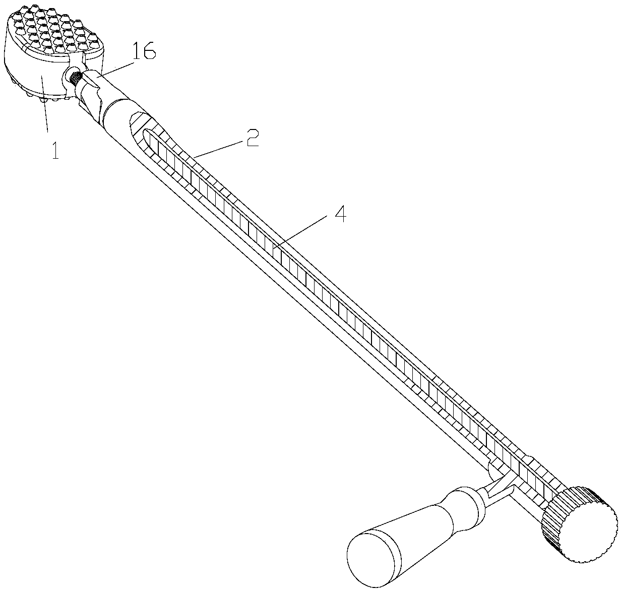
[0036] refer to image 3 , 4 , this embodiment is basically the same as Embodiment 1, the difference lies in that the structures of the positioning protrusions and the positioning concave holes are different. Two convex prisms 16 are arranged at the front of the positioning bump, and the two convex prisms 16 are symmetrically arranged on both sides of the inner hole. Slot 17.

Embodiment 3

[0038] refer to Figure 5 , this embodiment is basically the same as the second embodiment, the difference is that the nail tip of the ratchet nail 8 is inclined toward the direction of the injection rod to prevent withdrawal.


PUM


Abstract

The invention discloses a bone cement type interbody fusion cage and an operation method thereof, and belongs to the field of interbody fusion cages for spinal operation. The interbody fusion cage comprises a bone cement type fusion device, an injection rod and a mounting screw, an injection through hole is formed in the injection rod, one end of the injection rod is opened, the other end of the injection rod is provided with a positioning protrusion, and an inner hole which is coaxial with the injection through hole is formed in the positioning protrusion; an end cover is arranged at one endof the mounting screw, a threaded head is arranged at the other end of the mounting screw, the mounting screw penetrates through the injection through hole of the injection rod, and the threaded headis in threaded connection with the bone cement type fusion device; a cavity is formed in the bone cement type fusion device, the work surface is provided with a plurality of barbed nails, long throughholes are formed in the barbed nails, short through holes are formed in the working surface, and a threaded hole and positioning concave holes are formed in the bone cement type fusion device. The interbody fusion cage can inject bone cement into the adjacent segmental vertebral bodies through the long and short through holes, and the interbody fusion cage is instantly fused with adjacent segments into a whole body to obtain stability.

Description

technical field [0001] The invention relates to an intervertebral fusion device used in spinal surgery and an operation method thereof, in particular to an operation method of a bone cement type intervertebral fusion device. Background technique [0002] Conventional intervertebral fusion devices are mainly used in spinal surgery, such as: spinal instability surgery requires fixed fusion, cervical and lumbar disc herniation, discectomy, lumbar spondylolisthesis surgery, etc. In conventional cages, autologous bone or a mixture of autologous bone and allograft bone is placed into the intervertebral space, embedded tightly, and then implanted into the intervertebral space. The stabilization of the spine is achieved by allowing the implanted bone to fuse with the adjacent vertebral bone. What must be implanted in the middle is bone tissue. It is necessary to wait until the bone heals to obtain initial stability, which takes about 3-6 months, and it usually takes two years for ...

Claims


Application Information

Patent Timeline
Patent Type & Authority Applications(China)
IPC IPC(8): A61F2/44A61F2/46
CPCA61F2/4455A61F2/4601A61F2/4611
Inventor 唐朝阳
Owner 唐朝阳
Learn More