Pipeline catalytic reactor for liquid phase

A catalytic reaction and pipeline technology, applied in chemical/physical processes, chemical instruments and methods, etc., can solve the problems of insufficient reaction of liquid phase reactants, short catalyst contact time, increased equipment cost, etc., and achieve scientific and reasonable stage number setting, Short reaction time, easy to manufacture and realize the effect

Pending Publication Date: 2018-09-18
QINZHOU UNIV
View PDF0 Cites 0 Cited by
  • Summary
  • Abstract
  • Description
  • Claims
  • Application Information

AI Technical Summary

Problems solved by technology

[0003] At present, when a fixed-bed reactor performs a liquid-phase catalytic reaction, the liquid-phase reactant is transported to the fixed-bed reactor through a pipeline. Because the flow rate of the liquid-phase reactant is too fast, the contact time with the catalyst is short, resulting in a liquid phase. The reactants are not fully reacted, so the amount of product is not high
If it is necessary to decelerate the flow rate of the liquid-phase reactant, it is necessary to replace the large-diameter delivery pipe or use other delivery drives to provide resistance. On the one hand, the pipeline is difficult to install, and on the other hand, the equipment cost is greatly increased.
In addition, the reactants need to be transported through pipelines and then reacted in a fixed-bed reactor. The transport and reaction are carried out separately, which not only takes a long time for the reaction, but also has high economic costs.

Method used


Image

  • Pipeline catalytic reactor for liquid phase

Examples


Embodiment Construction

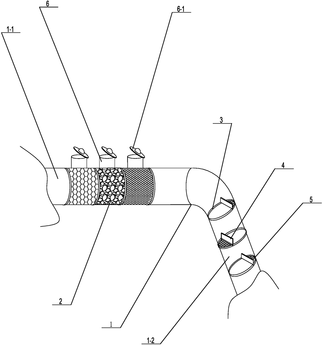
[0017] Such as figure 1 Propose a kind of specific embodiment of the present invention as shown, the pipeline catalytic reaction device that liquid phase is used, comprise reaction pipeline 1, described reaction pipeline 1 comprises the deceleration branch pipe 1-1 that horizontally arranges and the reaction branch pipe 1-1 that obliquely arranges downwards 2. The front end of the deceleration branch pipe 1-1 is connected to the liquid phase reactant delivery system, and the rear end of the reaction branch pipe 1-1 is connected to the product return system. In this embodiment, the deceleration branch pipe 1-1 and the reaction branch pipe 1-2 are set. Both are cylindrical and hollow with equal diameters, and in order to ensure the strength of the entire reaction pipeline, the reaction branch pipe 1-1 and the reaction branch pipe 1-2 are integrally formed; the deceleration branch pipe 1-1 is provided with several sections of ceramic ball joints 2, The ceramic ball joints 2 are a...


PUM


Abstract

The invention discloses a pipeline catalytic reaction device for a liquid phase. The pipeline catalytic reaction device for the liquid phase comprises a reaction pipeline, wherein the reaction pipeline comprises a deceleration branch pipe and a reaction branch pipe, and a plurality of segments of ceramic ball joints are arranged in the deceleration branch pipe; a plurality of partition plates arearranged in parallel in the reaction branch pipe, and the partition plate is provided with an overflow plate and meshes. The ceramic ball joints of which the ceramic ball diameters are gradually increased are arranged in the deceleration branch pipe, and the flow rate of a liquid phase reactant is reduced by a physical means; the plurality of partition plates are arranged in parallel in the reaction branch pipe, and the contact time between the liquid phase reactant and a catalyst is effectively prolonged due to the blocking of the overflow plates; the liquid phase reactant reacts once while passing through one partition plate, so that the reactant fully reacts, the amount of the product is increased, and the transport and the reaction are integrated into one body, thereby shortening the total reaction time. The catalytic reaction device has a simple structure, is easy to manufacture, has low economic cost, and good practicability, and is suitable for widespread promotion.

Description

technical field [0001] The invention relates to a chemical reaction device, in particular to a pipeline catalytic reaction device for liquid phase. Background technique [0002] Fixed bed reactor, also known as packed bed reactor, is a reactor filled with solid catalyst or solid reactant to realize heterogeneous reaction process. The solids are usually granular, with a particle size of about 2 to 15 mm, and are piled up into a bed of a certain height (or thickness). The bed is stationary and the fluid passes through the bed to react. The difference between it and the fluidized bed reactor and moving bed reactor is that the solid particles are in a static state. Fixed bed reactors are mainly used to realize gas-solid phase catalytic reactions, such as ammonia synthesis towers, sulfur dioxide contact oxidizers, hydrocarbon steam reformers, etc. When used in gas-solid or liquid-solid non-catalytic reactions, the bed is filled with solid reactants. The trickle bed reactor ca...

Claims


Application Information

Patent Timeline
Patent Type & Authority Applications(China)
IPC IPC(8): B01J8/06
CPCB01J8/06B01J8/008
Inventor 王伟建战浩李芳杰王学锋石海信张海燕
Owner QINZHOU UNIV
Why Eureka
Try Eureka