High-speed laser cladding and turning integrated machine device

A laser cladding, all-in-one technology, applied in other manufacturing equipment/tools, manufacturing tools, etc., can solve the problems affecting the uniformity of coating thickness and the quality of the cladding layer, so as to reduce workstations and processes and improve product quality , the effect of reducing production costs

Pending Publication Date: 2018-09-18
ACUNITY TIANJIN CO LTD
View PDF0 Cites 18 Cited by
  • Summary
  • Abstract
  • Description
  • Claims
  • Application Information

AI Technical Summary

Problems solved by technology

[0006] The present invention aims to solve the problem that the prior and subsequent processes of turning the existing shaft parts before high-speed laser cladding often affect the uniformity of the coating thickness and the quality of the cladding layer due to the deviation of the axis center due to the multiple disassembly and clamping of the parts. To solve the technical problems, a high-speed laser cladding and turning combined machine device is provided

Method used


Image

  • High-speed laser cladding and turning integrated machine device
  • High-speed laser cladding and turning integrated machine device
  • High-speed laser cladding and turning integrated machine device

Examples


specific Embodiment approach 1

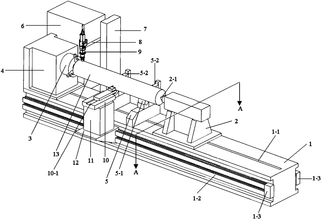
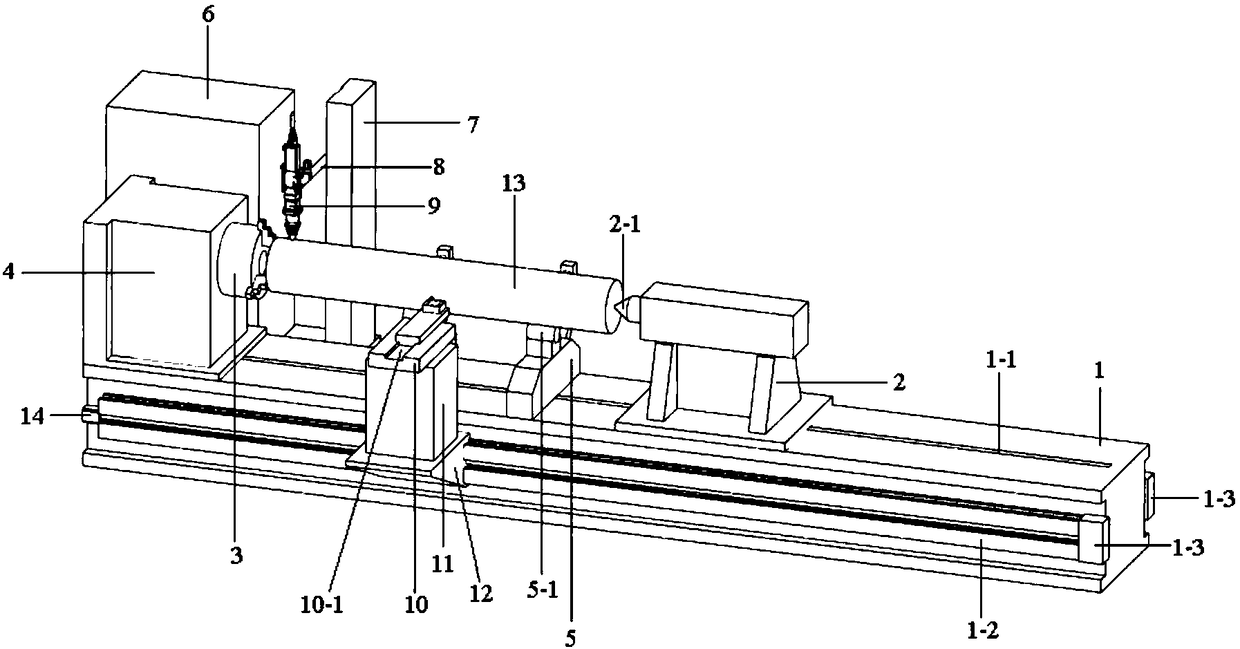
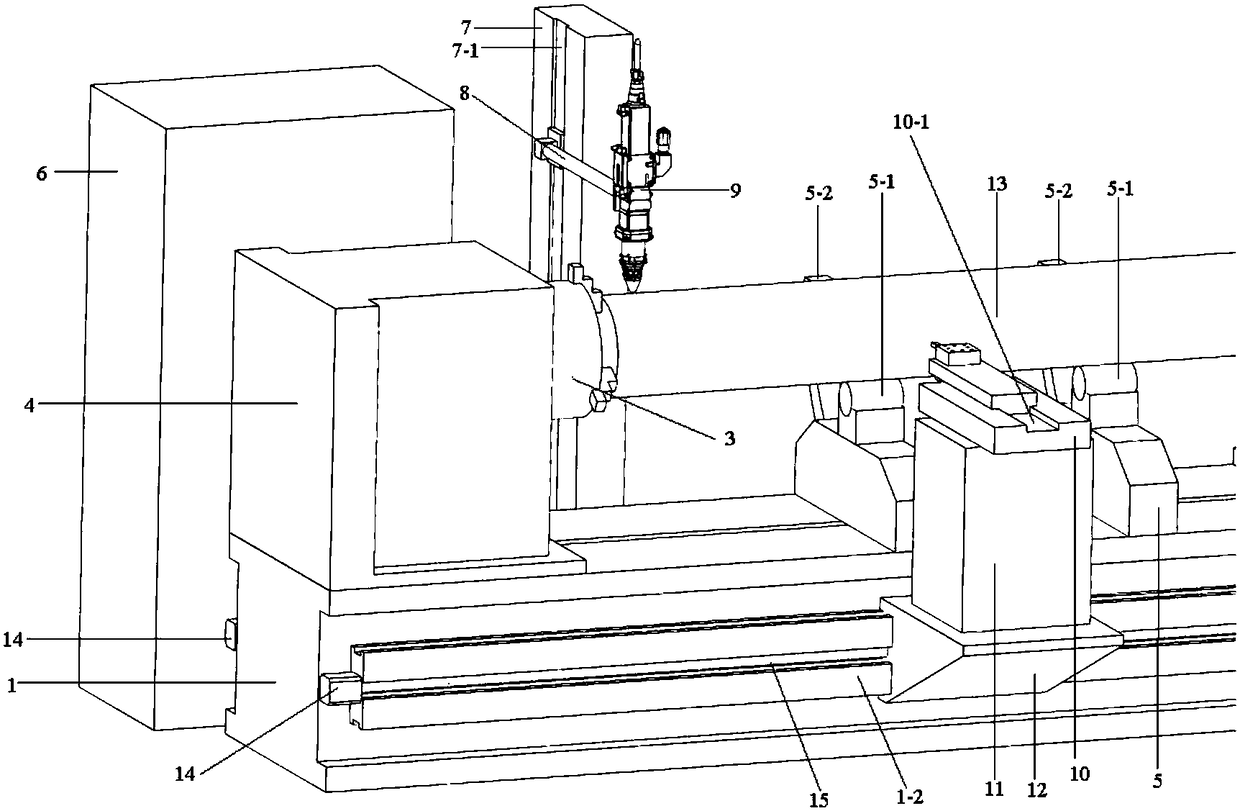
[0028] Specific implementation mode 1: This implementation mode is a high-speed laser cladding and turning composite integrated machine device, such as Figure 1-Figure 9 As shown, it is specifically composed of machine tool 1, tailstock 2, three-jaw chuck 3, headstock 4, support seat 5, control box 6, laser head fixed body 7, telescopic rod 8, laser head 9, turning tool holder 10, Turning tool holder base 11, turning tool holder sliding table 12, motor 14, first ball screw 15, second ball screw 16, third ball screw 17 and laser head fixed body sliding table 18;

[0029] The center of the upper end surface of the machine tool 1 is provided with a through groove 1-1, and the described through groove 1-1 penetrates the upper end surface of the machine tool 1, and the first slideway 1-2 and the second slideway 1-2 are respectively arranged on the two sides of the machine tool 1. Two slideways 1-4, the through groove 1-1, the first slideway 1-2 and the second slideway 1-4 are para...

specific Embodiment approach 2

[0040] Embodiment 2: The difference between this embodiment and Embodiment 1 is that the motor 14 is a servo motor. Others are the same as the first embodiment.

specific Embodiment approach 3

[0041] Embodiment 3: This embodiment differs from Embodiment 1 or Embodiment 2 in that: the turning tool holder 10 is a four-station turning tool holder. Others are the same as those in Embodiment 1 or 2.


PUM


Abstract

The invention discloses a high-speed laser cladding and turning integrated machine device, and relates to a laser cladding device. The high-speed laser cladding and turning integrated machine device aims to solve the technical problem that before high-speed laser cladding of existing shaft parts, the parts in front and back processes often deviate from the axis due to multiple-times disassembling,assembling and clamping during turning. The high-speed laser cladding and turning integrated machine device is composed of a machine tool, a tail seat, a head seat, a supporting seat, a tool holder,a tool holder sliding table and a laser head fixed body sliding table. Slideways are separately arranged on the two side faces of the machine tool, and the tool holder sliding table and the laser headfixed body sliding table are separately arranged on the two slideways. A tool holder base is fixed to the upper end face of the tool holder sliding table, and a laser head fixed body is fixed to theupper end face of the laser head fixed body sliding table. The tail seat and the head seat are arranged at two ends of the upper end face of the machine tool, and the supporting seat is arranged between the head seat and the tail seat. According to the high-speed laser cladding and turning integrated machine device, two processes of numerical control turning and laser cladding are arranged in onestation and carried out simultaneously to improve production efficiency, and at the same time, the condition of axial deviation caused by repeated clamping of the parts is avoided.

Description

technical field [0001] The invention relates to a high-speed laser cladding device. Background technique [0002] Laser cladding uses a high-power laser as a heat source to rapidly heat and melt the surface of the part material and the added alloy or ceramic powder. After solidification, a surface coating with special properties can be formed on the surface of the metal part to improve the wear resistance of the part surface. A surface strengthening method for corrosion resistance, heat resistance, oxidation resistance and other properties. [0003] In the traditional conventional laser cladding process, the laser directly heats the part substrate to form a molten pool, and the additional powder falls into the molten pool and melts to form a thick coating with a thickness of 1mm to 5mm. Therefore, for the part, the heat input is large and the dilution rate of the bonding surface is relatively low. high. Due to its limited surface accuracy and large machining allowance, the...

Claims


Application Information

Patent Timeline
Patent Type & Authority Applications(China)
IPC IPC(8): B23P23/04
CPCB23P23/04
Inventor 王威李俐群陶汪洪臣
Owner ACUNITY TIANJIN CO LTD
Why Eureka
Try Eureka