Electronically controlled diesel injector

A technology for injectors and diesel oil, which is applied in the direction of fuel injection devices, special fuel injection devices, machines/engines, etc. It can solve the problems that affect the control accuracy of diesel injector injection oil volume, large injection delay, slow response speed, etc., to avoid Increased fuel oil return temperature, reduced failures, and fast response

Active Publication Date: 2020-09-29
龙口龙泵柴油喷射高科有限公司
View PDF10 Cites 0 Cited by
  • Summary
  • Abstract
  • Description
  • Claims
  • Application Information

AI Technical Summary

Problems solved by technology

[0003] For the purpose of facilitating the installation of the engine, the electromagnet part of the electronically controlled diesel injector commonly used in the prior art is placed on the upper part, so as to be far away from the nozzle part, so that the distance between the electrical part and the executive part is relatively long, and a transmission mechanism needs to be set between the two. It leads to slow response speed and large injection delay, which affects the injection fuel quantity control accuracy of diesel injectors
In addition, because most of the oil nozzle parts commonly used in the prior art have an oil return structure, and a good sealing effect is required between the needle valve and the needle valve body, it is necessary to consider the sealing isolation between the high pressure oil and the low pressure oil, the structure is complicated, and the processing is difficult

Method used


Image

  • Electronically controlled diesel injector
  • Electronically controlled diesel injector
  • Electronically controlled diesel injector

Examples


Embodiment Construction

[0022] The principles and features of the present invention are described below in conjunction with the accompanying drawings, and the examples given are only used to explain the present invention, and are not intended to limit the scope of the present invention.

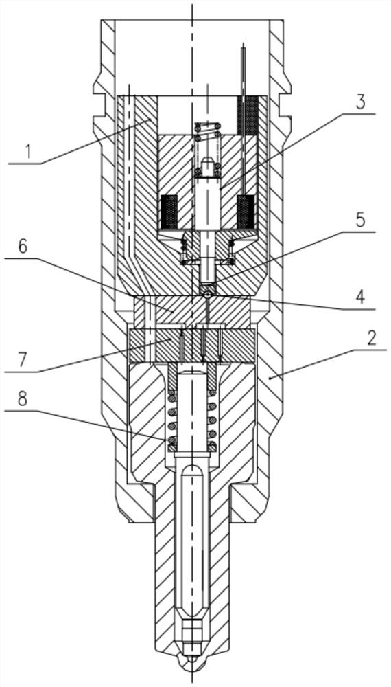
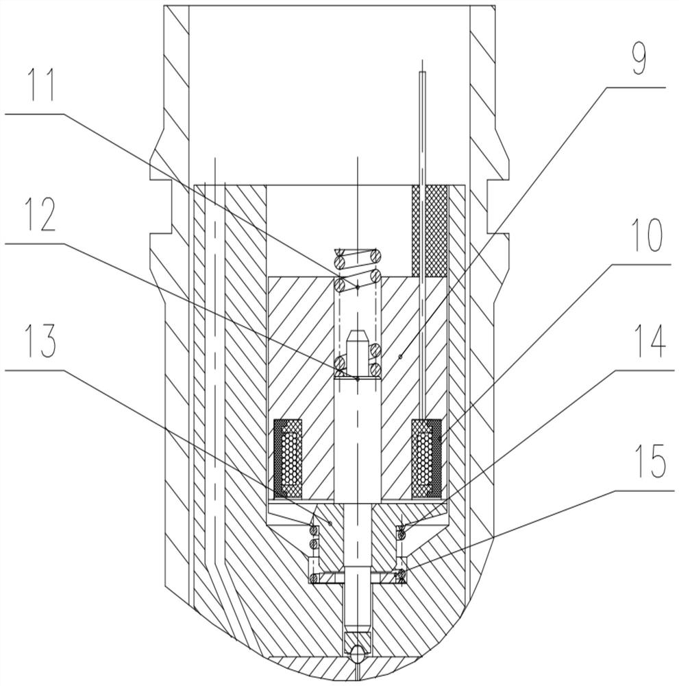
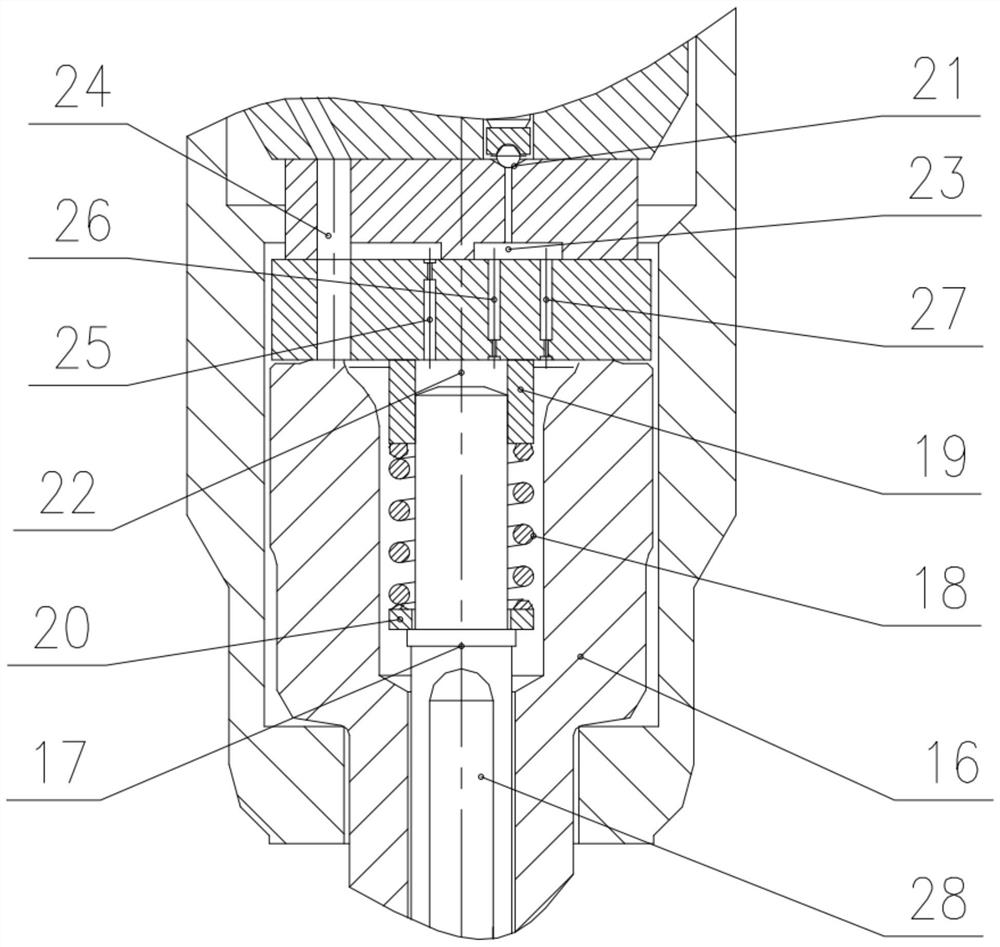
[0023] like figure 1 , figure 2 , image 3 As shown, an electronically controlled diesel injector includes an injector body (1), a tight cap (2), an electromagnet component (3), a sealing ball (4), a ball seat (5), an upper transition block (6 ), the lower transition block (7) and the nozzle part (8). The electromagnet parts include iron core (9), coil (10), electromagnet spring (11), valve stem (12), armature (13), armature spring 14, spring washer 15, and the electromagnet part is arranged on the fuel injector In the cavity of the body 1, the electromagnet components include an iron core 9, a coil 10, an electromagnet spring 11, a valve stem 12, an armature 13, an armature spring 14, and a spring washer 15, an...


PUM


Abstract

The invention discloses an electronically controlled diesel injector which comprises an oil injector body, a locking nut, an electromagnet part, a seal ball, a ball seat, an upper transition block, alower transition block and an oil nozzle part. A needle valve is matched with an upper spring seat; the upper spring seat is matched with the lower transition block; a lower spring seat is connected with the needle valve; a needle valve spring is matched with the upper spring seat and the lower spring seat; the oil injector body, the upper transition block, the lower transition block and a needlevalve body are sequentially connected; the ball seat is matched with an inner wall of the oil injector body in a sealing way, and is connected with the electromagnet part; the lower transition block,the upper spring seat and the needle valve form a control cavity; the upper transition block, the lower transition block and an upper conical surface form a pressure cavity; an oil inlet channel is arranged in the oil injector body, the upper transition block and the lower transition block, and communicates with an inner cavity of the needle valve body; the lower transition block is provided witha left oil channel, a middle oil channel and a right oil channel; the oil inlet channel communicates with the control cavity; the control cavity communicates with the pressure cavity; the pressure cavity communicates with the oil inlet channel; the upper end of the needle valve spring is matched with the upper spring seat; and the lower end of the needle valve spring is matched with the lower spring seat.

Description

technical field [0001] The invention relates to the technical field of an electronically controlled high-pressure common rail injection device for a diesel engine, in particular to an electronically controlled diesel injector for injecting diesel into a combustion chamber of an engine. Background technique [0002] With the advancement of technology and the improvement of emission requirements, the fuel injection system of diesel engines has gradually developed from mechanical to electronically controlled. Since the electronically controlled high-pressure common rail diesel injection system can achieve timing, quantitative, flexible and controllable fuel injection, it has gradually become a market mainstream technology, among which diesel injector is the key and core component. [0003] For the purpose of facilitating the installation of the engine, the electromagnet part of the electronically controlled diesel injector commonly used in the prior art is placed on the upper p...

Claims


Application Information

Patent Timeline
Patent Type & Authority Patents(China)
IPC IPC(8): F02M47/02F02M61/10F02M61/16F02M61/18
CPCF02M47/027F02M61/10F02M61/16F02M61/1893F02M2200/16F02M2200/9053
Inventor 郭兴王会军吴俐璋贾玉杰刘本学张海涛战经波蒋金喜
Owner 龙口龙泵柴油喷射高科有限公司
Why Eureka
Try Eureka