core melt trap

A technology of core melt and melt, which is applied in the field of nuclear power, can solve the problems of low cooling efficiency of the core catcher, achieve the effects of weakening the accumulation effect, simplifying the post-accident treatment, and improving the coolability

Active Publication Date: 2020-05-05
CHINA NUCLEAR POWER ENG CO LTD
View PDF27 Cites 0 Cited by
  • Summary
  • Abstract
  • Description
  • Claims
  • Application Information

AI Technical Summary

Problems solved by technology

[0004] In the prior art, when a nuclear accident occurs, the melt flows into the core catcher, and the cooling efficiency of the core catcher is low

Method used


Image

  • core melt trap
  • core melt trap
  • core melt trap

Examples


Embodiment 1

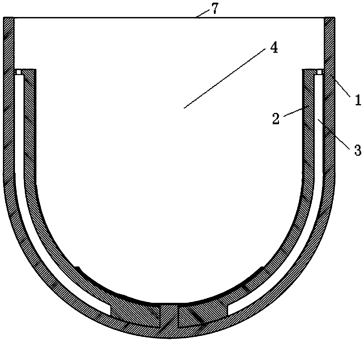
[0034] Such as figure 1 As shown, this embodiment provides a core melt collection device, comprising a collection cylinder 1 in the form of a crucible for collecting core melt, located below the pressure vessel of the reactor, and the pressure vessel of the reactor is arranged on In the pit of the reactor, the bottom of the pit of the reactor is connected to the opening of the catch cylinder through a communication channel, and the core melt collection device also includes a first partition assembly 2, which separates the catch cylinder 1 At least two trapping chambers are nested sequentially from outside to inside, and the inlet of the trapping chamber communicates with the opening 7 of the trapping cylinder.

[0035] Specifically, the first partition assembly 2 separates the collection cylinder 1 into two collection chambers arranged sequentially from outside to inside, namely the first collection chamber 3 and the second collection chamber 4, the first partition The assemb...

Embodiment 2

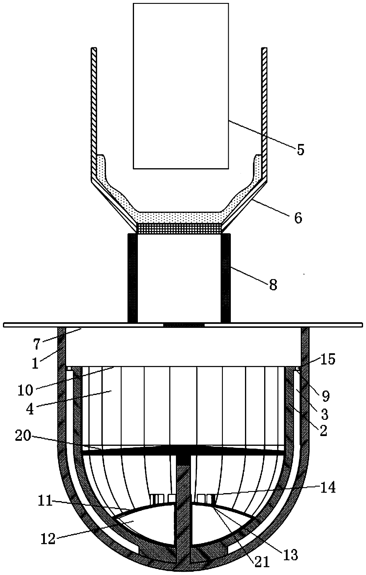
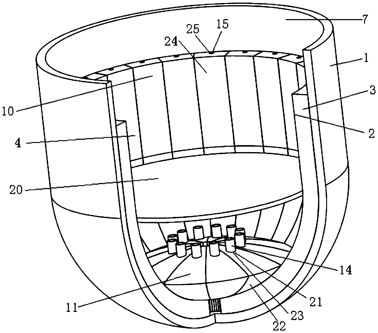
[0039] Such as Figure 2-6 As shown, the present embodiment provides a core melt collection device, comprising a collection cylinder 1 in the form of a crucible for collecting core melt, located below the reactor pressure vessel 5, and the reactor pressure vessel 5 It is arranged in the reactor pit 6, and the bottom of the reactor pit 6 is connected with the opening 7 of the catch cylinder through a communication channel 8. The core melt trap also includes a first partition assembly 2, which will The collection cylinder 1 separates at least two collection chambers nested in sequence from outside to inside, and the inlet of the collection chamber communicates with the opening 7 of the collection cylinder.

[0040] Specifically, the first partition assembly 2 separates the collection cylinder 1 into two collection chambers arranged sequentially from outside to inside, namely the first collection chamber 3 and the second collection chamber 4, the first partition The assembly 2 i...

Embodiment 3

[0063] This embodiment provides a core melt collection device, which differs from the core melt collection device in Embodiment 2 in that: the elevation of the inlet of the inner collection chamber in this embodiment is located at: 100% of the stack The retention of core melt corresponds to 20% of its liquid level elevation, and the elevation of the inlet of the trap chamber closest to the inner wall of the trap cylinder is located at: 95% of its liquid level corresponding to 100% core melt retention .


PUM


Abstract

The invention discloses a reactor core melt trapping device. The reactor core melt trapping device comprises a trapping cylinder having a crucible form and used for trapping a reactor core melt, the trapping cylinder is located below the pressure vessel of a reactor, the pressure vessel of the reactor is arranged in the reactor pit of the reactor, the bottom of the reactor pit of the reactor is connected with the opening of the trapping cylinder by a communication channel, the reactor core melt trapping device further comprises a first partition assembly, the first partition assembly divides the trapping cylinder into at least two trapping chambers which are sequentially sleeved from the outside to the inside, and the inlets of the trapping chambers are communicated with the opening of thetrapping cylinder. When severe nuclear accidents occur, the first partition assembly divides the trapping cylinder into the at least two trapping chambers which are sequentially sleeved from the outside to the inside, so the coolability of the melt is enhanced, the cooling efficiency of the melt is improved, the volume of the trapping device is effectively reduced, the melt is reduced in areas, the accident post-treatment of the reactor is greatly simplified, and the radiation dose received by workers is effectively reduced.

Description

technical field [0001] The invention belongs to the technical field of nuclear power, and in particular relates to a reactor core melt collection device. Background technique [0002] After the serious accidents at the Three Mile Island and Chernobyl nuclear power plants, the nuclear power industry began to focus on research and research on the prevention and mitigation of severe accidents. Due to engineering and other requirements. When a serious accident occurs in a pressurized water reactor nuclear power plant, the loss of core waste heat removal means will evaporate and exhaust the coolant, the core will be exposed and continue to heat up, the fuel elements will melt due to the loss of cooling, and the core melt will fall into the pressure vessel ( RPV) lower chamber, which in turn causes the failure of the lower head of the pressure vessel. If effective measures cannot be taken to cool it, the core melt may melt through the pressure vessel. After the pressure vessel m...

Claims


Application Information

Patent Timeline
Patent Type & Authority Patents(China)
IPC IPC(8): G21C9/016
CPCG21C9/016Y02E30/30
Inventor 邢继荆春宁宋代勇元一单韩旭朱晨
Owner CHINA NUCLEAR POWER ENG CO LTD
Why Eureka
Try Eureka