Directly-driven centrifugal separation device

A centrifugal separation and direct-drive technology, applied to centrifuges with rotating drums, centrifuges, etc., can solve the problems of complex manufacturing process, inability to clean solids on-line, and inability to feed materials on-line

Active Publication Date: 2018-09-21
唐凌霄
View PDF12 Cites 5 Cited by
  • Summary
  • Abstract
  • Description
  • Claims
  • Application Information

AI Technical Summary

Problems solved by technology

Nevertheless, desktop centrifuges still have relatively fatal defects: (1) Solids cannot be cleaned online: that is, solids are washed while the rotor is rotating, which cannot simulate the actual situation in production and provide necessary centrifugation operation data for production in advance; (2) Online feeding is not possible: that is, feeding is carried out while the rotor is rotating; (3) A precise trimming barrel is required for centrifugation, and a single sample cannot be centrifuged; (4) The loading capacity of the barrel is limited and cannot well meet various needs
However, the existing various centrifuges or solid-liquid separators have complex structures, and it is difficult to fix and take out the centrifuge drum. At the same time, the cleaning of the centrifuge is also time-consuming and laborious, and the manufacturing process is complicated, expensive, and the repair and maintenance costs are high. Various defects or disadvantages, can not better meet the needs of the complete separation of solid-liquid mixture in the laboratory test and pilot test

Method used


Image

  • Directly-driven centrifugal separation device
  • Directly-driven centrifugal separation device
  • Directly-driven centrifugal separation device

Examples


Embodiment 1

[0183] The driving system of this embodiment is an external rotor motor, and its detailed structural diagram is shown in the attached Figure 6 .

[0184] as attached Figure 6 Shown, centrifugal turntable (6-9) and centrifugal bowl (6-4) are independent parts. The independent top cover (6-1) that seals the centrifuged liquid collection chamber (6-17) is fixed on the top of the chamber wall (6-3) of the centrifuged liquid collection chamber by its top cover fixing structure (6-25), and passes through the door The lock (6-26) is locked tightly; the center of the top cover has a feeding hole. The drum top cover (6-27) of the sealed centrifugal drum, the turntable connection structure (6-6) located outside the bottom of the centrifugal drum (6-4) and the centrifugal drum body are integrally formed; the centrifugal drum Connect and fix with the drum connection structure (6-18) located outside the centrifugal turntable (6-5) through the turntable connection structure located at ...

Embodiment 2

[0189] In this embodiment, the drive system is an external rotor motor, and its detailed structural diagram is shown in the attached Figure 7 .

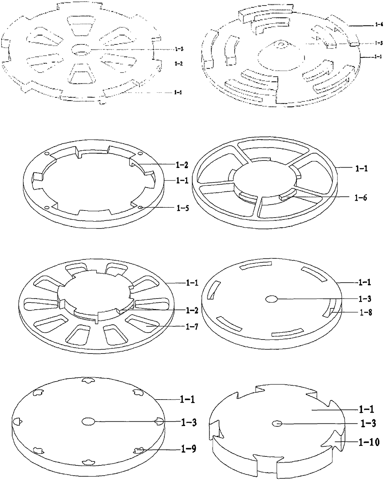
[0190] as attached Figure 7 As shown, the independent top cover (7-1) of the sealed centrifuged liquid collection chamber (7-6) is connected to the connection structure 1 (7-2) on the top of the centrifuged liquid collection chamber wall through the connecting structure 2 (7-3) on its outside. ) to rotate and lock each other to fix the top cover (see the attachment for the connection structure Picture 1-1 and attached Pic 4-1 ); the center of the top cover has a feeding hole; the drum top cover (7-22) of the sealed centrifugal drum passes through the connecting structure 4 (7- 25) Mutual rotation and clamping to realize the fixation of the top cover (connection structure see attached Figure 1-2 and attached Pic 4-1 ).

[0191] as attached Figure 7 As shown, the cooling coil (7-4), the base (7-11), the stator assembly (7-1...

Embodiment 3

[0195] In this embodiment, the drive system is an inner rotor motor, and its detailed structural diagram is shown in the attached Figure 8 .

[0196] as attached Figure 8 As shown, the connection mode between the top cover (8-1) of the sealed centrifugal liquid collection chamber and the cavity wall is the same as that of embodiment 2; the connection mode between the centrifugal drum and the drum top cover of the sealed centrifugal drum is the same as that of embodiment 2; The circular hole in the center of the top cover that seals the centrifuged liquid collection chamber is the feeding hole (8-9) for the solid-liquid mixture to be centrifuged.

[0197] as attached Figure 8 As shown, the cooling coil (8-2), the stator assembly (8-7) and the front end cover (8-8) are integrally molded with a plastic sealant to form the cavity wall of the centrifugal liquid collection cavity, and the center of the bottom is respectively surrounded by a The circular cavity on the outside a...


PUM


Abstract

The invention discloses a directly-driven centrifugal separation device. The device comprises a motor rotor integrated with a centrifugal rotating disc to form a whole body and a centrifugal rotatingdrum or a centrifugal rotor used as an independent component; or the device comprises a motor rotor integrated with a centrifugal rotating disc to form a whole body and a motor stator; the position ofa motor air gap port led to one side of a ring-shaped groove is higher than the inner surface of the bottom of the ring-shaped groove with a liquid discharging opening; a gap connected with the motorair gap is sealed in any position led to one side of the ring-shaped groove; a target material is isolated from the motor air gap by sealing the gap. The directly-driven centrifugal separation devicehas the advantages that the motor rotor of the device and the centrifugal rotating drum or the centrifugal rotor can switch between a locked state and an unlocked state; all the parts of the device are convenient to manufacture; the whole device is convenient to assemble; the device is high in safety, quiet and stable in operation and easy to maintain, clean and check, and can overcome various defects or disadvantages of the existing solid-liquid separation device.

Description

[0001] This application is a divisional application with an application date of March 23, 2015, application number CN201510128476.8, application publication number CN105251624A, and the title of the invention is "a direct-drive centrifugal separation device". technical field [0002] The invention relates to a direct-drive centrifugal separation device and its use method, in particular to a small-scale solid-liquid mixture centrifugal separation device and its use method, which can be used in laboratories to remove gram-level to kilogram-level solids from solid-liquid mixtures. Completely separate and clean the equipment thoroughly. Background technique [0003] In the laboratory test and pilot test research and industrial production process, we often encounter the need to completely separate the solid-liquid mixture and wash the solid to obtain a solid or liquid that meets the requirements. The solid-liquid separation equipment often used in industrial production is a varie...

Claims


Application Information

Patent Timeline
Patent Type & Authority Applications(China)
IPC IPC(8): B04B1/00B04B9/04B04B7/08B04B11/06
Inventor 唐凌霄杨开富杨艳黄良凤
Owner 唐凌霄
Why Eureka
Try Eureka