Liquor fumigation-washing steam generator

A steam generator and generator technology, used in steam generation, steam generation methods, steam boilers, etc., can solve the problems of poor gas flow in the combustion space, low content of active ingredients, and low degree of intelligence, so as to avoid excessive heating. Uniform, fast heat transfer, and the effect of improving heat transfer speed

Active Publication Date: 2018-09-21
SHANDONG INST FOR FOOD & DRUG CONTROL
View PDF6 Cites 0 Cited by
  • Summary
  • Abstract
  • Description
  • Claims
  • Application Information

AI Technical Summary

Problems solved by technology

The current steam generator is also widely used in the treatment of various diseases, especially in the treatment of chronic diseases caused by aging and old damage to muscles and ligaments, such as CN2167709Y patent, but in the current prior art, such as CN2167709Y Patent, because the steam is generated directly by heating, the temperature of the generated steam will be too high, and it will cause too much moisture in the generated steam, and the drug may be deposited in the lower part because it is a particle, so the ejected steam is effective The content of ingredients is too low, and the temperature is too high, and the degree of intelligence in the existing technology is not high, and effective intelligent operation cannot be carried out
[0005] In the background technology, when the gas is used to heat the steam generator, the gas either directly heats the water tank, or generates steam through secondary heat exchange, especially directly heats the water tank, and uses the convective heat exchange inside the water tank to perform the fluid convection exchange between the upper and lower parts of the water tank. heat, but in this case, the heat fluid in the lower part needs to flow naturally to the upper part, and the heat transfer efficiency is low
[0006] In the background technology, the inventor has developed such as figure 1 The above-mentioned structure has a great improvement in improving heat energy absorption, but because the heat pipe evaporation end extends to the combustion space, the gas flow in the combustion space is not good, and the combustion cannot be fully carried out, and the cost of the background technology is relatively high, so this The application has carried out further improvement on the basis of the background technology

Method used


Image

  • Liquor fumigation-washing steam generator
  • Liquor fumigation-washing steam generator
  • Liquor fumigation-washing steam generator

Examples


Embodiment Construction

[0041] The specific embodiments of the present invention will be described in detail below in conjunction with the accompanying drawings.

[0042] In this article, if there is no special explanation, when it comes to formulas, " / " means division, and "×" and "*" mean multiplication.

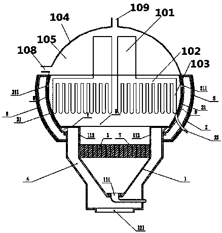
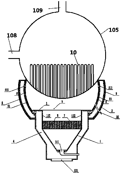
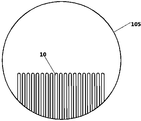
[0043] Such as Figure 2-6 Disclosed is a gas-fired steam generator utilizing a heat pipe, the steam generator includes a burner and a water tank 105, the water tank 105 includes a water inlet 108, the combustion of the burner will heat the water in the water tank 105, and the steam will generate The device also includes a heat pipe 10 arranged in the water tank 105, such as figure 2 As shown, the heat pipe 10 is arranged inside the water tank 105 and extends upward from the bottom of the water tank 105. There are multiple heat pipes 10, and the bottom of the lower end of the heat pipe is connected to the inner wall of the water tank.

[0044]Traditional gas steam generators use gas to directl...


PUM


Abstract

The invention provides a fuel steam generator. The fuel steam generator comprises a combustor and a water tank, wherein the water tank comprises a water inlet and a steam outlet; the water tank is arranged at the upper part of the combustor; a plurality of heat tubes which extend upwards from the bottom of the water tank are arranged in the water tank; and the bottoms of the lower ends of the heattubes are connected to the inner wall of the water tank. The fuel steam generator is improved in the way that the heat tubes are arranged at the bottom of the water tank; owing to the characteristicof high heat transfer speed of the heat tubes, heat energy is quickly transferred to the upper part of the water tank, so that the heat transmission speed of heat energy is improved, and the demand onthe heat absorption capability can be further met.

Description

technical field [0001] The invention relates to a steam generator technology, in particular to a steam generator of a heat pipe with a new structure. Background technique [0002] Heat pipe technology is a heat transfer element called "heat pipe" invented by George Grover of Los Alamos National Laboratory in the United States in 1963. It makes full use of the principle of heat conduction and phase change medium. The rapid heat transfer properties of the heat pipe quickly transfer the heat of the heating object to the heat source, and its thermal conductivity exceeds that of any known metal. [0003] Heat pipe technology was widely used in aerospace, military and other industries before. Since it was introduced into the radiator manufacturing industry, people have changed the traditional radiator design ideas and got rid of the single heat dissipation mode that only relies on high air volume motors to obtain better heat dissipation. The use of heat pipe technology enables th...

Claims


Application Information

Patent Timeline
Patent Type & Authority Applications(China)
IPC IPC(8): F22B1/00F22B31/08A61H33/06
CPCA61H33/065F22B1/00F22B31/08
Inventor 谢强胜李启艳刁飞燕王坤王小兵钟兵黄雪涛
Owner SHANDONG INST FOR FOOD & DRUG CONTROL
Why Eureka
Try Eureka