
Method for simultaneously measuring particle size and refractive index

A measurement method and particle size technology, applied in measurement devices, particle and sedimentation analysis, phase influence characteristic measurement, etc., can solve problems affecting particle size measurement accuracy, etc., and achieve the effect of high measurement accuracy

Active Publication Date: 2018-09-21
TIANJIN UNIV
View PDF3 Cites 4 Cited by
  • Summary
  • Abstract
  • Description
  • Claims
  • Application Information

AI Technical Summary

Problems solved by technology

Therefore, in the measurement of particle size based on light scattering, such as spray fields, the appropriate scattering angle is usually selected so that the particle scattered light is insensitive to the refractive index, that is, the refractive index is considered constant, but due to heating or chemical reactions, the refractive index varies with Particle size changes, such as particles in the atmosphere, particles in the combustion field, etc., which affects the particle size measurement accuracy

Method used


Image

  • Method for simultaneously measuring particle size and refractive index
  • Method for simultaneously measuring particle size and refractive index
  • Method for simultaneously measuring particle size and refractive index

Examples


Embodiment Construction

[0022] Embodiments of the present invention will be further described in detail below in conjunction with the accompanying drawings.

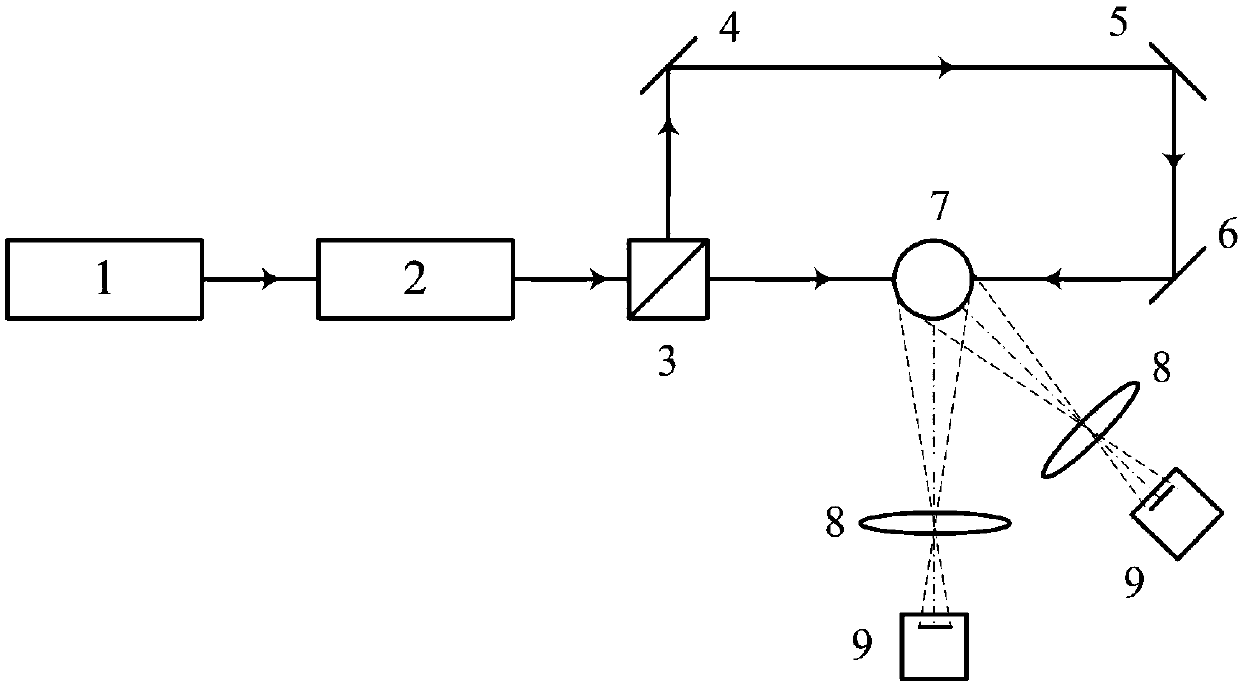
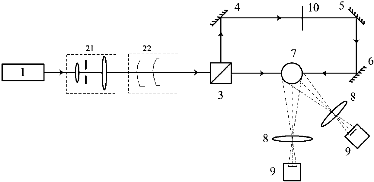
[0023] by figure 2 The shown experimental optical path is an example, setting forth the concrete measuring process of measuring method of the present invention:

[0024] Step 1. Optical path system construction and particle fringe image and / or focus image acquisition

[0025] according to figure 2 Build an optical path system, including laser 1, beam expander and collimator system 21, beam compression system 22, beam splitter 3, mirrors 4, 5 and 6, particles 7, imaging lens 8, CCD 9, and shutter 10. Laser 1 is a vertically polarized semiconductor laser with a wavelength of λ=532nm and a maximum power of 1.5W. The thin beam emitted by the laser 1 is expanded, filtered, and collimated into a circular beam with a diameter of 20mm after being expanded, filtered, and collimated by the system 21; then compressed into a sheet-shaped beam with a l...


PUM


Abstract

The invention discloses a method for simultaneously measuring the particle size and the refractive index. The method includes the steps that two sheet light beams with the equal intensity are used foroppositely irradiating a particle, and in a 90-degree scattering angle area and a lateral scattering angle area, focused images and / or interference fringe patterns which are formed through particle scattered light are / is simultaneously recorded, wherein in the 90-degree scattering angle area, the focused images or the interference fringe patterns, formed through p=0 order reflected light on the particle surface, of the two opposite light beams are recorded, and in the lateral scattering angle area, the focused image or the interference fringe pattern formed through p=0 order reflected light and p=1 order refracted light generated after any single light beam passes through the particle is recorded; focused two-point-image intervals or / and the fringe quantity of the fringe patterns collected in the 90-degree scattering angle area and the lateral scattering angle area are extracted, and through calculation, the particle size d and the refractive index n are obtained. The noncontact measurement method has the advantages of being simple in principle, high in measurement accuracy, high in practicability and the like, and can be used for simultaneously measuring a spraying particle field, the aerosol particle size and the refractive index.

Description

technical field [0001] The invention relates to a particle parameter measurement technology, in particular to a method for simultaneously measuring particle diameter and refractive index based on light scattering imaging. Background technique [0002] Particle size and its refractive index are important parameters of particles. The real part of the refractive index and the size are closely related to the scattered light characteristics of the particles. Particles with different chemical compositions have different refractive indices. The larger the size of the same particle, the more concentrated the scattered light is in the small forward angle range. Therefore, in the measurement of particle size based on light scattering, such as spray fields, the appropriate scattering angle is usually selected so that the particle scattered light is insensitive to the refractive index, that is, the refractive index is considered constant, but due to heating or chemical reactions, the re...

Claims


Application Information

Patent Timeline
IPC IPC(8): G01N15/02G01N21/41
CPCG01N15/0227G01N21/41
Inventor 吕且妮尉小雪葛宝臻张晗笑
Owner TIANJIN UNIV
Learn More