Matching method of radio frequency antenna of tire pressure monitoring sensor based on valve core antenna

A technology of tire pressure monitoring and radio frequency antenna, applied in tire measurement, impedance matching network, electrical components, etc., can solve problems such as poor customer experience effect, poor anti-interference performance of antenna, false alarm of receiver, etc., to solve communication instability , shorten the development cycle, and solve the effect of short service life

Active Publication Date: 2018-09-25
SHENZHEN HANGSHENG ELECTRONICS
View PDF6 Cites 1 Cited by
  • Summary
  • Abstract
  • Description
  • Claims
  • Application Information

AI Technical Summary

Problems solved by technology

[0004] 1. The front-mounted TPMS usually adopts a built-in sensor solution. The sensor module is separated from the outside world by wheels, which makes the anti-interference design of the sensor module’s antenna very difficult. There are generally problems of low transmission efficiency and serious system data loss.
When passing through the complex traffic electromagnetic environment, due to the poor anti-interference performance of the antenna, the sensor module is frequently disconnected from the receiver, which affects the performance of the entire TPMS;
[0005] 2. Since the rear-mounted TPMS mostly adopts an external solution, the antenna matching of the sensor module is easy to design

Method used


Image

  • Matching method of radio frequency antenna of tire pressure monitoring sensor based on valve core antenna
  • Matching method of radio frequency antenna of tire pressure monitoring sensor based on valve core antenna
  • Matching method of radio frequency antenna of tire pressure monitoring sensor based on valve core antenna

Examples


Embodiment Construction

[0027] In order to make the object, technical solution and advantages of the present invention clearer, the present invention will be further described in detail below in conjunction with the accompanying drawings and embodiments. It should be understood that the specific embodiments described here are only used to explain the present invention, not to limit the present invention.

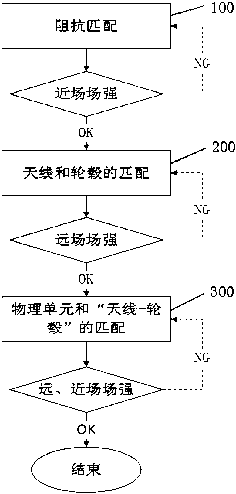
[0028] The matching method of the radio frequency antenna of the tire pressure monitoring sensor based on the valve core antenna in the embodiment of the present invention reasonably combines the antenna impedance matching theory, electromagnetic field and electromagnetic wave theory with the production process and working conditions of the tire pressure monitoring sensor, and has undergone a large number of antenna matching tests. , far and near field strength test, bench test and real vehicle road test, eliminate the secondary factors one by one, find out the main factors affecting the antenna tra...


PUM


Abstract

The invention relates to the technical field of radio frequency debugging, in particular to a matching method of a radio frequency antenna of a tire pressure monitoring sensor based on a valve core antenna. The matching method comprises the following steps: performing impedance matching on the antenna of the tire pressure monitoring sensor through an impedance matching network; mounting the tire pressure monitoring sensor that completes the antenna impedance matching on a hub, adjusting an impedance matching network parameter of the antenna, and detecting the antenna radiation field strength in a far field for matching and debugging; step C, when the tire pressure monitoring sensor that completes the antenna and hub matching is sealed by filling rubber, isolating rubber filling of a circuit component in the impedance matching network affected by sealing by filling rubber, and adjusting the impedance matching network parameter of the isolated circuit component, so as to complete the matching of a physical unit and 'the antenna plus the hub'. The method in the invention improves the emission intensity of the sensor and the radiation efficiency of the antenna, and solves the problem that the communication between the sensor and the receiver is unstable.

Description

technical field [0001] The invention relates to the technical field of radio frequency debugging, in particular to a matching method of a tire pressure monitoring sensor radio frequency antenna based on a valve core antenna. Background technique [0002] During the high-speed driving of a car, tire failure, especially a puncture, often catches the driver off guard due to its accidental and unpredictability, which is also one of the important reasons for sudden traffic accidents. In recent years, with the extensive deepening and application of automobile driving safety systems, in order to prevent tire blowouts and change passive safety into active safety, automobile tire pressure real-time monitoring system (Tire Pressure Monitoring System, TPMS) is gradually becoming an indispensable guarantee for vehicle driving safety. safety device. The TPMS system mainly consists of two parts: the tire pressure monitoring sensor installed on the wheel hub of the car and the receiver in...

Claims


Application Information

Patent Timeline
IPC IPC(8): H04B1/04H04B1/18H03H11/28
CPCH03H11/28H04B1/0458H04B1/18B60C23/0494
Inventor 毛泽龙
Owner SHENZHEN HANGSHENG ELECTRONICS
Why Eureka
Try Eureka