
Automatic bending and welding equipment for door and window pipe materials

A welding equipment and pipe technology, which is applied in the field of automatic bending and welding equipment, can solve the problems that cannot be directly applied to right-angle welding of stainless steel square pipes.

Active Publication Date: 2018-09-28
济南萨博特种汽车有限公司
View PDF7 Cites 8 Cited by
  • Summary
  • Abstract
  • Description
  • Claims
  • Application Information

AI Technical Summary

Problems solved by technology

[0005] Chinese patent number: CN201520372298.9 An automatic square tube welding machine for welding square tubes and flanges, the square tube welding machine includes a machine base; a square tube fixing device, the square tube fixing device is arranged on the machine base, used For fixing the square tube; the square tube rotating device, the square tube rotating device is set on the machine base, the upper end is provided with a rotating platform for placing the flange, and the lower end of the square tube is docked with the flange; and at least one set of square tube welding device , the square tube welding device is set on the side of the rotating platform through a translation device, the square tube welding device is equipped with a welding torch, and the welding torch corresponds to the junction of the square tube and the flange, which solves the problem of automatic welding of the square tube and the flange work, but it cannot be directly applied to the right-angle welding of stainless steel square tubes

Method used


Image

  • Automatic bending and welding equipment for door and window pipe materials
  • Automatic bending and welding equipment for door and window pipe materials
  • Automatic bending and welding equipment for door and window pipe materials

Examples


Embodiment Construction

[0047] Below in conjunction with accompanying drawing and embodiment of description, specific embodiment of the present invention is described in further detail:

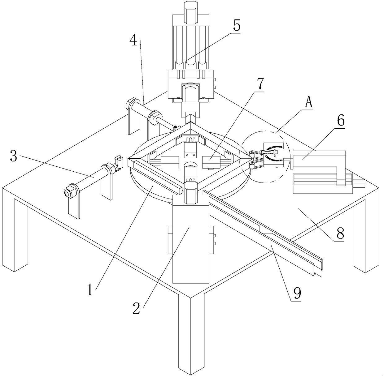
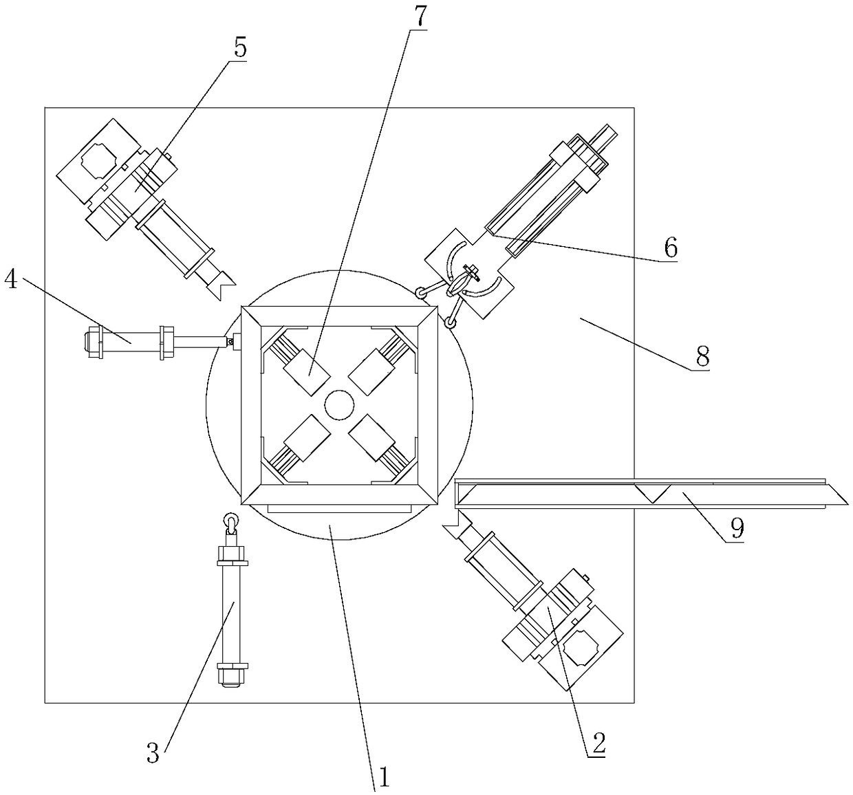
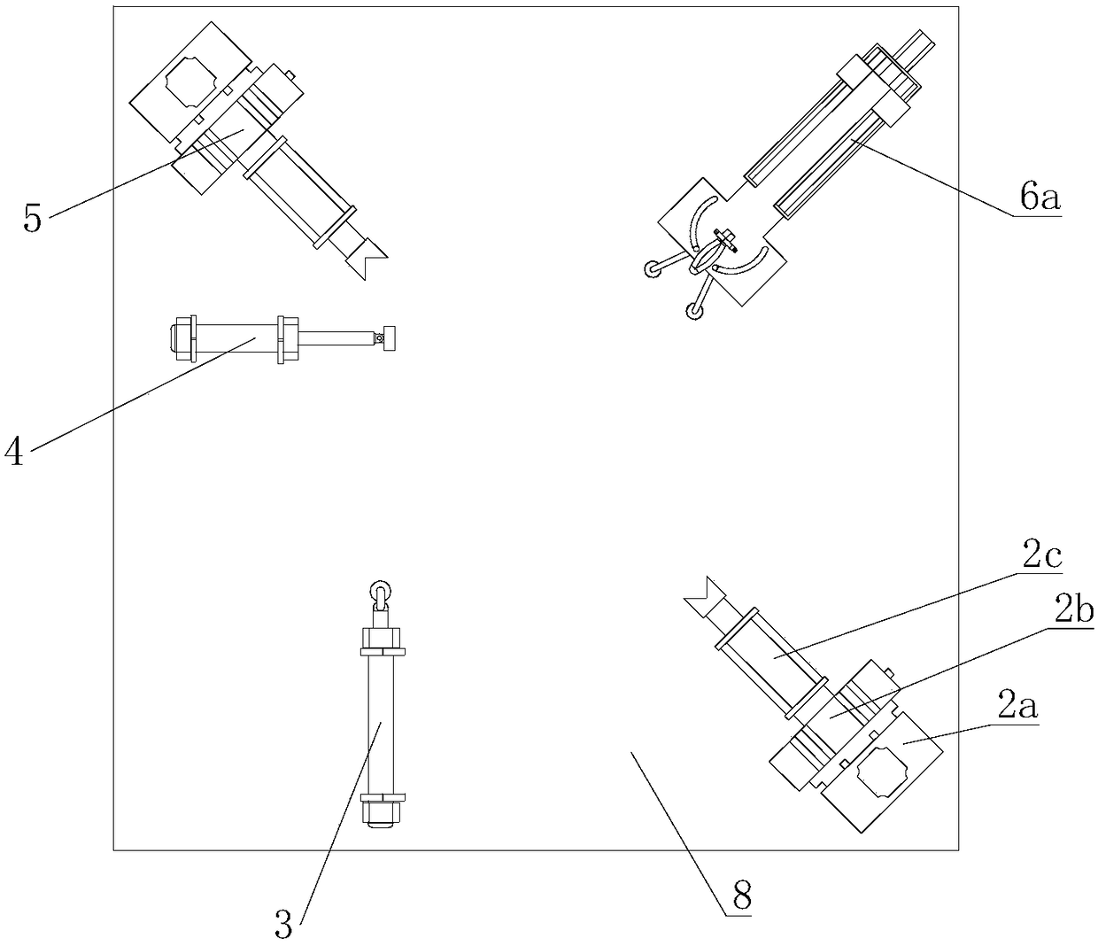
[0048] refer to Figure 1 to Figure 10 The shown automatic bending and welding equipment for doors and windows pipes includes a base 8, and also includes a rotary table 1, a first turning arm 2, a first bending assembly 3, a second bending assembly 4, The second overturning mechanical arm 5 and the welding assembly 6, the rotary table 1 includes a step indexing disk 1a and a rotating disc 1b, the stepping indexing disk 1a is horizontally installed on the base 8, and the step The output end of the progressive indexing plate 1a is set upward, and the rotating disc 1b is horizontally set on the output end of the stepping indexing plate 1a, and the clamping assembly 7 for fixing the square tube is also arranged on the rotating disc 1b, so The first overturning mechanical arm 2, the first bending assembly 3, the second ...


PUM


Abstract

The invention relates to the field of automatic machining, in particular to automatic bending and welding equipment for door and window pipe materials. The automatic bending and welding equipment comprises a base and further comprises a rotary workbench, a first overturning mechanical arm, a first bending assembly, a second bending assembly, a second overturning mechanical arm and a welding assembly. The rotary workbench comprises a stepping type index plate and a rotary disc. The rotary disc is provided with a clamping assembly used for fixing a square pipe. The first overturning mechanical arm, the first bending assembly, the second bending assembly, the second overturning mechanical arm and the welding assembly are sequentially arranged in the output direction of the rotary disc, and the first overturning mechanical arm, the first bending assembly, the second bending assembly, the second overturning mechanical arm and the welding assembly are all arranged on the base. The output endof the first overturning mechanical arm and the output end of the second overturning mechanical arm are arranged oppositely and extend in the axis direction of the rotary disc. By means of the automatic bending and welding equipment, bending of the stainless steel square pipes and the right angle welding work are achieved.

Description

technical field [0001] The invention relates to the field of automatic processing, in particular to an automatic bending and welding equipment for door and window pipes. Background technique [0002] Stainless steel pipes are often used in the production materials of existing doors and windows. Stainless steel is the abbreviation of stainless acid-resistant steel. The steel grades that are resistant to weak corrosive media such as air, steam, water, or have stainless properties are called stainless steel; Steel grades that are chemically etched and corroded by chemicals such as acid, alkali, and salt are called acid-resistant steels. [0003] Due to the difference in chemical composition of the two, their corrosion resistance is different. Ordinary stainless steel is generally not resistant to chemical medium corrosion, while acid-resistant steel is generally stainless. The term "stainless steel" does not simply refer to one kind of stainless steel, but refers to more than ...

Claims


Application Information

Patent Timeline
Patent Type & Authority Applications(China)
IPC IPC(8): B23P23/04
CPCB23P23/04
Inventor 车国容
Owner 济南萨博特种汽车有限公司
Learn More