
Post-treatment device for the cleaning of automobile parts

A technology for post-treatment devices and auto parts, applied in special treatment targets, water/sewage treatment, water/sewage treatment equipment, etc., can solve the problem of not being able to automatically add flocculants, flocculants and sewage, and achieve simple structure and tightness. Good, avoid the effect of tight fit

Inactive Publication Date: 2018-09-28
重庆聚伯雅科技有限公司
View PDF7 Cites 0 Cited by
  • Summary
  • Abstract
  • Description
  • Claims
  • Application Information

AI Technical Summary

Problems solved by technology

[0003] The present invention intends to provide a post-cleaning treatment device for auto parts to solve the problem that the flocculant cannot be added automatically and the flocculant and sewage can be stirred

Method used


Image

  • Post-treatment device for the cleaning of automobile parts
  • Post-treatment device for the cleaning of automobile parts
  • Post-treatment device for the cleaning of automobile parts

Examples


Embodiment 1

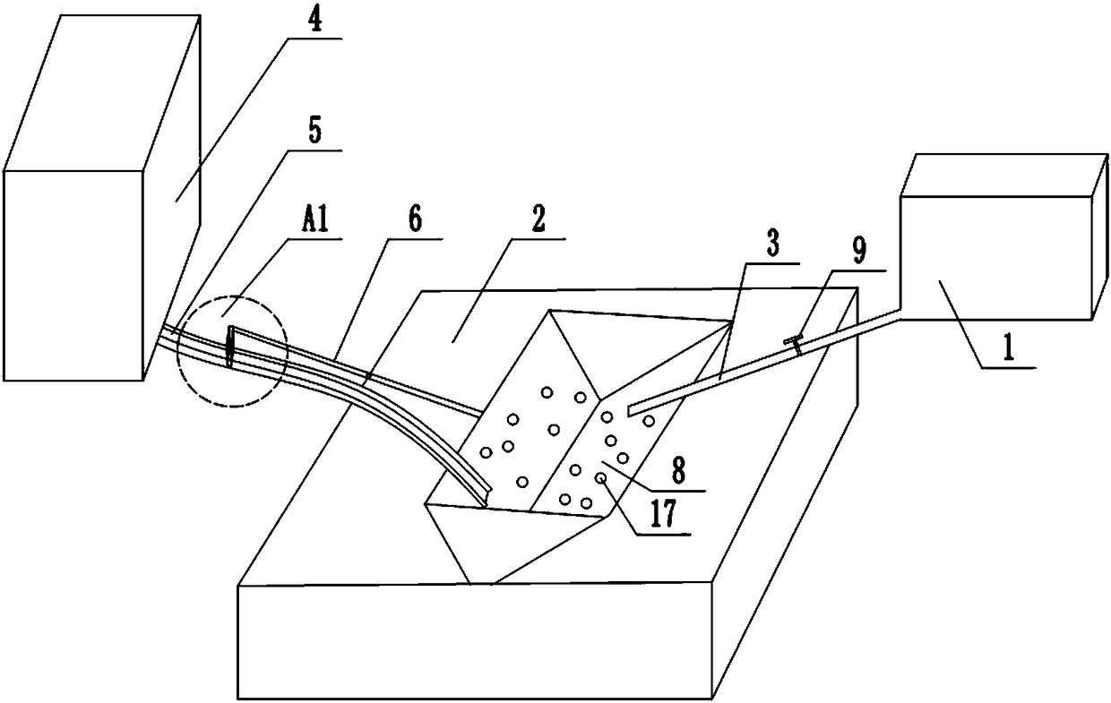
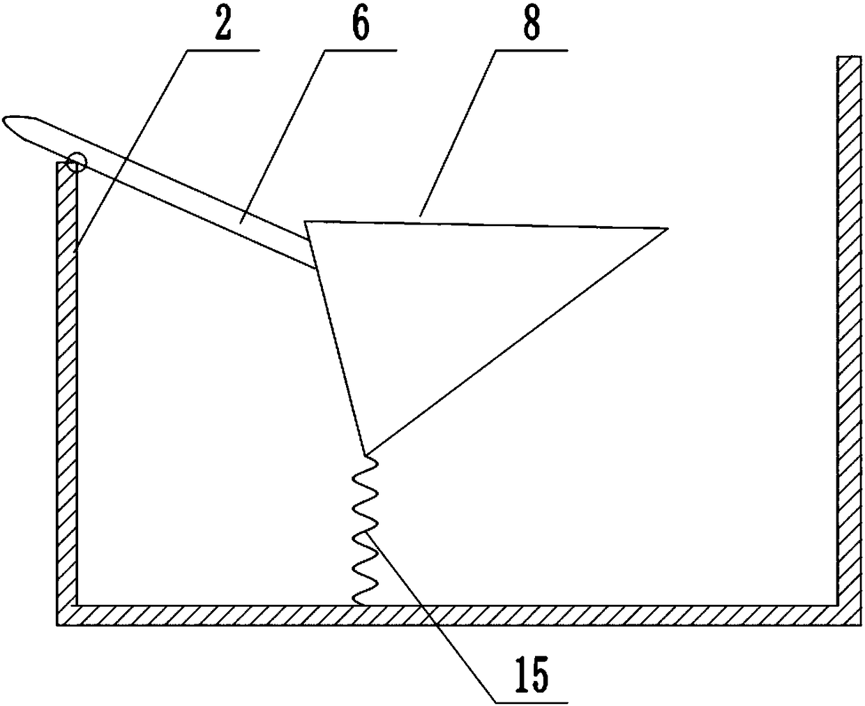
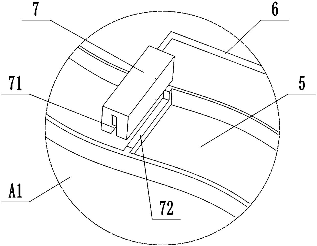
[0027] Such as figure 1 , image 3 As shown, the auto parts cleaning post-processing device includes a sewage conveying mechanism 1 and a sedimentation tank 2, and also includes a flocculant supply mechanism. The flocculant supply mechanism includes a storage part 4, a reaction pool 8, and a channel for guiding the flocculant into the reaction pool 8 5. There is a gate 7 on the channel 5, and a long shaft 6 is hinged on the wall of the sedimentation tank 2. The right end of the long shaft 6 is fixedly connected with the reaction tank, and the left end of the long shaft 6 is fixedly connected with the switch of the gate 7. There are several Tapered rubber holes. Such as figure 2 As shown, there is a compression spring 15 between the bottom of the reaction tank 8 and the sedimentation tank 2 , and the water outlet of the sewage conveying mechanism 1 is above the reaction tank 8 . Among them, such as image 3 , Figure 4 As shown, the channel 5 that guides the flocculant to...

Embodiment 2

[0032] Such as Figure 5 As shown, the difference between the auto parts cleaning post-processing device and the first embodiment is that the water valve 9 is a gate valve, which includes a fixedly connected gate 10 and a handle 13. Because the gate 10 and the handle 13 are fixedly connected, the handle The movement of 13 can drive the gate 10 to move so as to achieve the purpose of controlling whether the water flow passes; there is a spring between the gate 10 and the water pipe 3, so after the handle 13 loses the pressing force of the semi-disc 11, the gate 10 is supported by the spring 14 The force falls to keep the water valve closed. Wherein the incomplete rotating disc is a half disc, and the axis center of the half disc rotation is below the handle. When the half disc 11 rotates around the rotating shaft 12, half of the time squeezes the handle 13 and half of the time leaves the handle 13, thereby achieving control. The purpose of intermittent switch of flashboard 10....

Embodiment 3

[0035] Such as Figure 6 As shown, the difference between the auto parts cleaning post-processing device and the second embodiment is that the incomplete turntable is a cam 16 . The smoother curve of the cam 16 will make the process of changing the force on the handle 13 a gradual process, so the water valve 9 that uses the structure of the cam 16 to control the opening and closing is less noisy, and the wear of the handle 13 is smaller, so the use of the water valve 9 Longer life.


PUM


Abstract

The invention relates to the technical field of equipment for sewage treatment, and particularly discloses a post-treatment device for the cleaning of automobile parts. The post-treatment device comprises a sewage conveying mechanism, a sedimentation tank and a flocculating agent feeding mechanism; the flocculating agent feeding mechanism comprises a storage part, a reaction tank, a channel for leading a flocculating agent into the reaction tank, and a gate arranged on the channel; a long shaft is hinged on the wall of the sedimentation tank; one end of the long shaft is fixedly connected withthe reaction tank; the other end of the long shaft is connected with the switch of the gate; the reaction tank is provided with tapered rubber holes dispersedly; and a pressure spring is arranged between the bottom of the reaction tank and the sedimentation tank. Through the adoption of the scheme, when sewage generated by washing automobile parts is processed, the flocculating agent can be automatically added when sewage enters the post-treatment device, and no flocculating agent is added when no sewage enters the post-treatment device.

Description

technical field [0001] The invention relates to the technical field of sewage treatment equipment. Background technique [0002] In automobile maintenance and overhaul, the cleaning of parts is a relatively important task. After each assembly is disassembled into parts, the oil stains, carbon deposits and scales of the parts should be removed, so that the assembly and vehicle assembly can proceed smoothly. Removing dirt, washing the inside and outside of the car and its assembly and parts can detect problems (such as abnormal wear, cracks, loosening, etc.) in time, so that corresponding measures can be taken to prevent unsafe hazards. However, the sewage after cleaning the parts contains various impurities. If it is not treated and allowed to flow out directly, it will cause serious environmental pollution, so it will generally be discharged into nature after a certain treatment, but there are some Problems, such as the flocculation process in sewage treatment, the current...

Claims


Application Information

Patent Timeline
IPC IPC(8): C02F1/52
CPCC02F1/5281C02F2201/002C02F2201/005C02F2303/14
Inventor 曾雨琳詹华山李涛黄诗鸿张小恒袁苗达
Owner 重庆聚伯雅科技有限公司
Learn More