Reinforced concrete cast-in-place frame structure of a building

A reinforced concrete and frame structure technology is applied in the field of reinforced concrete cast-in-place frame structures of buildings, which can solve the problems of trouble, affecting installation, and the inability to adjust the height or the distance between the left and right of the steel support structure, so as to improve the prefabrication rate and improve the overall seismic performance. , the effect of reducing seismic loads and foundation costs

Active Publication Date: 2019-12-06
厦门中建东北设计院有限公司
View PDF1 Cites 0 Cited by
  • Summary
  • Abstract
  • Description
  • Claims
  • Application Information

AI Technical Summary

Problems solved by technology

[0006] In order to solve the above-mentioned technical problems, the present invention provides a reinforced concrete cast-in-place frame structure of a building, to solve the traditional reinforced concrete cast-in-place frame of a building proposed in the above-mentioned background technology or adopt a cast-in-place shear wall structure to improve the seismic performance, Or the steel structure is welded to the steel bars in the reinforced concrete cast-in-place frame, which often needs to be connected with a long power cord, and it needs to be transported once for each welding layer, which is troublesome. However, the design of floor heights is not necessarily the same, and the height between the steel bars reserved for reinforced concrete cast-in-place columns and the distance between two sets of columns are also large or small. Small, and the overall steel support structure cannot adjust the height or the left and right distance, which affects the problem of later installation

Method used


Image

  • Reinforced concrete cast-in-place frame structure of a building
  • Reinforced concrete cast-in-place frame structure of a building
  • Reinforced concrete cast-in-place frame structure of a building

Examples


Embodiment

[0035] as attached figure 1 to attach Figure 9 Shown:

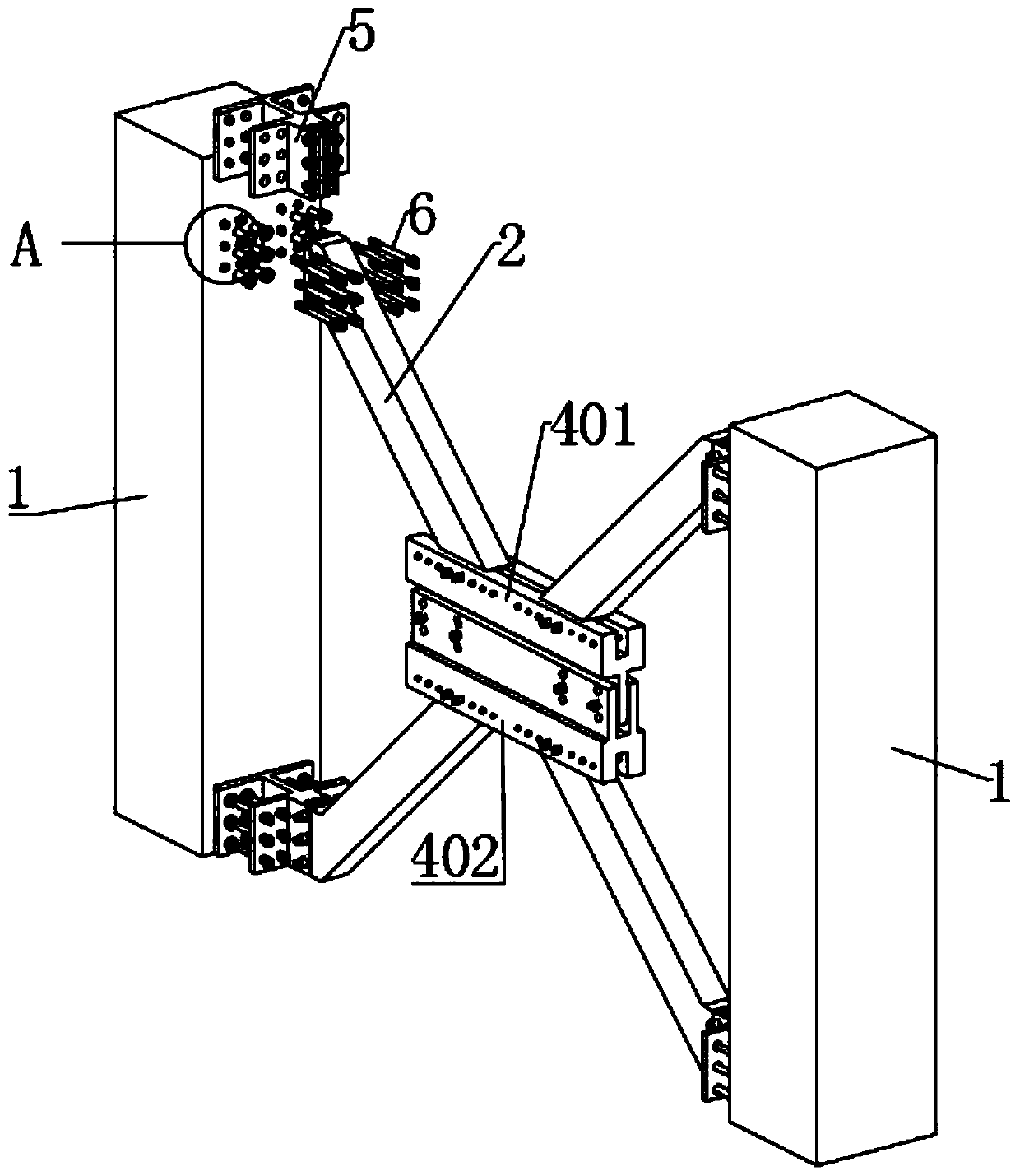
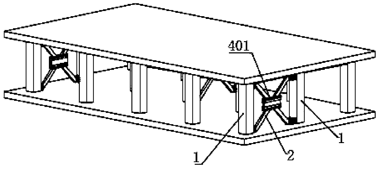
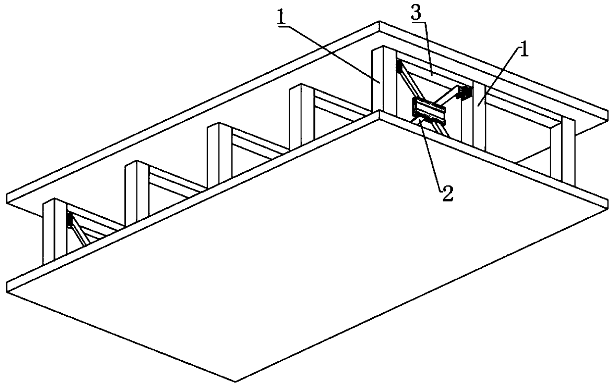
[0036]The invention provides a reinforced concrete cast-in-place frame structure of a building, which includes a reinforced concrete cast-in-place column 1, a reserved hole 101, a pre-embedded threaded steel bar 102, a diagonal connecting rod 2, a horizontal sliding plate 201, a horizontal insert plate 202, and a beam 3 , upper adjustment plate 401, lower adjustment plate 402, horizontal adjustment groove 403, vertical adjustment groove 404, vertical sliding plate 405, Shi-type connecting block 5, first perforation 501, second perforation 502, slot 503, threaded rod 6. Nut 601, connecting through hole A7, connecting through hole B8, T-shaped threaded sleeve 9 and internal threaded hole 901; the upper and lower inner sides of the reinforced concrete cast-in-place column 1 are provided with twelve sets of reserved holes 101, and the pre-embedded threaded steel bars 102 connected with the internal reinforcement of the rei...


PUM


Abstract

The invention provides a reinforced concrete cast-in-situ frame structure of a building. The reinforced concrete cast-in-situ frame structure comprises pre-embedded threaded steel bars, diagonal connecting rods, upper adjusting plates, lower adjusting plates and T-shaped threaded sleeves; reserved holes are internally provided with the pre-embedded threaded steel bars connected with steel bars inreinforced concrete cast-in-situ vertical columns correspondingly; the T-shaped threaded sleeves penetrate through first penetrating holes in rear side plates on connecting blocks shaped like a Chinese character 'shi' to be connected to threads of the pre-embedded threaded steel bars in a screwed mode, and one end of each threaded rod penetrates through a second penetrating hole and is screwed into an internal threaded hole in the corresponding T-shaped threaded sleeve; horizontal inserting plates are inserted into inserting grooves, and penetrate through connecting through holes B in the twosides of the inserting grooves and connecting through holes B in the horizontal inserting plates through the threaded rods, so that the diagonal connecting rods and the connecting blocks shaped like aChinese character 'shi' are connected together. Through arrangement of the upper adjusting plates and the lower adjusting plates, the heights of the adjusting plates can be adjusted according to theheights of the vertical columns, the positions of transverse sliding plates in transverse adjusting grooves can further be adjusted, and thus the reinforced concrete cast-in-situ frame structure is suitable for different distances between the two sets of vertical columns.

Description

technical field [0001] The invention belongs to the technical field of buildings, and more specifically relates to a reinforced concrete cast-in-place frame structure of a building. Background technique [0002] Earthquake is a sudden and extremely destructive natural disaster, which poses a serious threat to human society. my country is one of the areas in the world where earthquake disasters occur frequently. Actively responding to these earthquake disasters is an important task for building an urban and rural earthquake prevention and disaster reduction system. Due to the combination of steel and concrete, the composite frame not only saves the design amount of steel, but also the concrete flange can effectively restrain the local buckling instability of the steel beam and improve the ductility of the component. Compared with the steel frame, the composite frame has much higher stiffness and bearing capacity, and reduces the beam height and floor structure height. At the...

Claims


Application Information

Patent Timeline
Patent Type & Authority Patents(China)
IPC IPC(8): E04B1/343E04B1/98E04H9/02
CPCE04B1/34326E04H9/021E04H9/025
Inventor 董旭
Owner 厦门中建东北设计院有限公司
Why Eureka
Try Eureka