A drying structure for reducing the moisture content of log planks
A moisture content, wood board technology, applied in wood drying, static material dryers, drying chambers/containers, etc., can solve problems such as low efficiency, increased processing energy consumption, inability to effectively use limited space, etc., to achieve uniform heating, Consistent dryness
- Summary
- Abstract
- Description
- Claims
- Application Information
AI Technical Summary
Problems solved by technology
Method used
Image
Examples
Embodiment 1
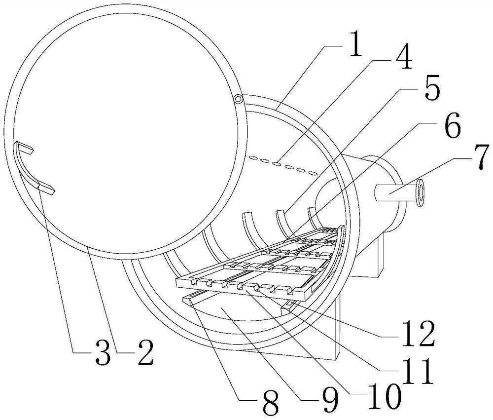
[0032] Such as figure 1 , 3 , 4, and 5, the present embodiment includes a tank body 1 and an end cap 2 for closing the tank body 1, a liquid collecting groove 9 is opened on the inner wall of the bottom of the tank body 1 along the axis of the tank body, and the liquid collecting tank 9 The two ends of the groove 9 are respectively provided with guide rails 8 parallel to the axis of the tank body 1, and a slide groove 12 is provided on the upper surface of each guide rail 8, and a plurality of grooves are opened on the inner wall of the top along the axis of the tank body 1. A suction hole 4, and a plurality of suction holes 4 communicate with the suction pipe 7 arranged on the outer wall of the tank body 1, and also include a rectangular bracket formed by splicing two transverse plates 6 and two longitudinal plates 10, and There is a slot 11 on the upper surface of each of the longitudinal plates 10, and a plurality of sliding blocks matched with the chute 12 are arranged in...
Embodiment 2
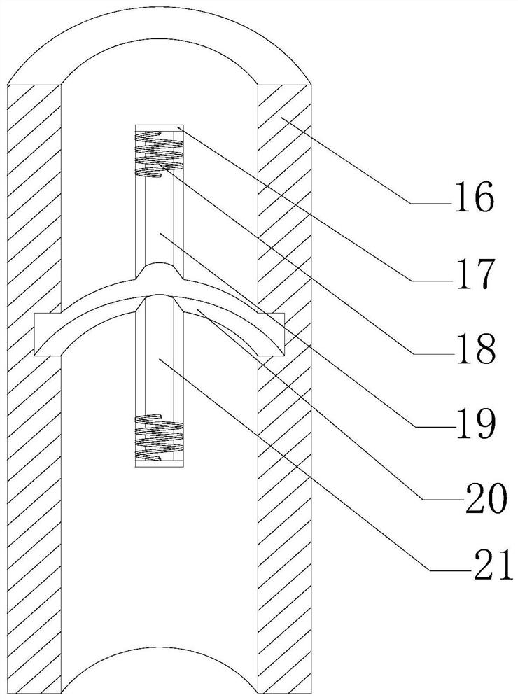
[0038] Such as Figure 1~5 As shown, in this embodiment, a limit cylinder 16 is provided on the top outer wall of the tank body 1 along the axial direction, a heat insulating base is provided on the upper surface of the tank body 1, and the cylinder 22 is arranged above the tank body 1 on the heat insulating base. , the pin 13 is connected to the inner side wall of the end cover 2 through a universal ball, and a through hole is opened on the top outer wall of the tank body 1, the pin 13 moves through the through hole, and the limit tube 16 is connected with the cylinder 22 The output end is connected, and a radial groove 20 is opened on the inner peripheral wall of the limit cylinder 16 along the circumferential direction, and a block 15 matched with the radial groove 20 is provided on the outer peripheral wall of the pin 13. An active groove I19 communicating with the radial groove 20 is formed on the inner wall of the limiting cylinder 16 away from the end cover 2 , and the ...
Embodiment 3
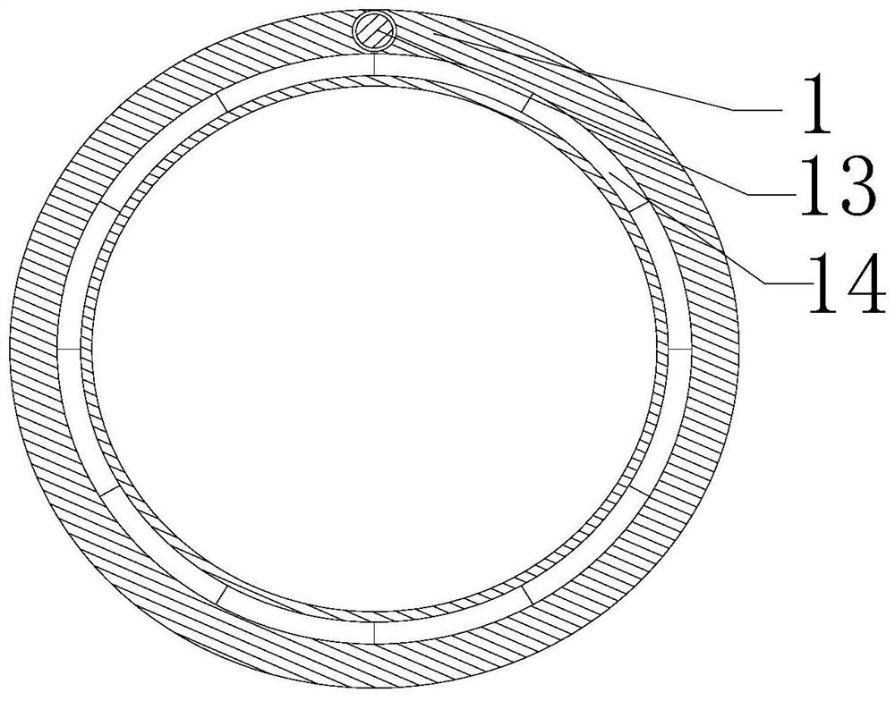
[0044] Such as figure 2 As shown, in this embodiment, a plurality of butt joint grooves 14 are provided on the open end surface of the tank body 1 along the circumference thereof, a rubber ring is provided on the inner side wall of the end cover 2, and a rubber ring is provided on the rubber ring. A plurality of rubber protrusions matched with the docking groove 14 . Further, since the tank body 1 is always in an airtight state during the drying process, and the end cap 2 is a movable part, the applicant provided a rubber ring on the inner side wall of the end cap 2, and at the same time along the circumferential direction of the rubber ring in its The inner wall is provided with a plurality of rubber protrusions, and the open end face of the tank body 1 is provided with a plurality of butt grooves 14 matched with the rubber protrusions, that is, when capping, through a plurality of rubber protrusions and rubber rings, the A plurality of different sealing sections are formed...
PUM
 Abstract
Description
Claims
Application Information
 - R&D
- Intellectual Property
- Life Sciences
- Materials
- Tech Scout
- Unparalleled Data Quality
- Higher Quality Content
- 60% Fewer Hallucinations
Browse by: Latest US Patents, China's latest patents, Technical Efficacy Thesaurus, Application Domain, Technology Topic, Popular Technical Reports.
© 2025 PatSnap. All rights reserved.Legal|Privacy policy|Modern Slavery Act Transparency Statement|Sitemap|About US| Contact US: help@patsnap.com


