Microparticle forward scattered light detection device and detection method thereof
A technology of forward scattered light and detection device, which is applied in the direction of measuring device, individual particle analysis, particle and sedimentation analysis, etc. It can solve the problems of cumbersome sample processing, inability to detect the size of micro particles on site, expensive detection equipment, etc. Small, low cost, high precision effect
- Summary
- Abstract
- Description
- Claims
- Application Information
AI Technical Summary
Problems solved by technology
Method used
Image

Examples
Embodiment
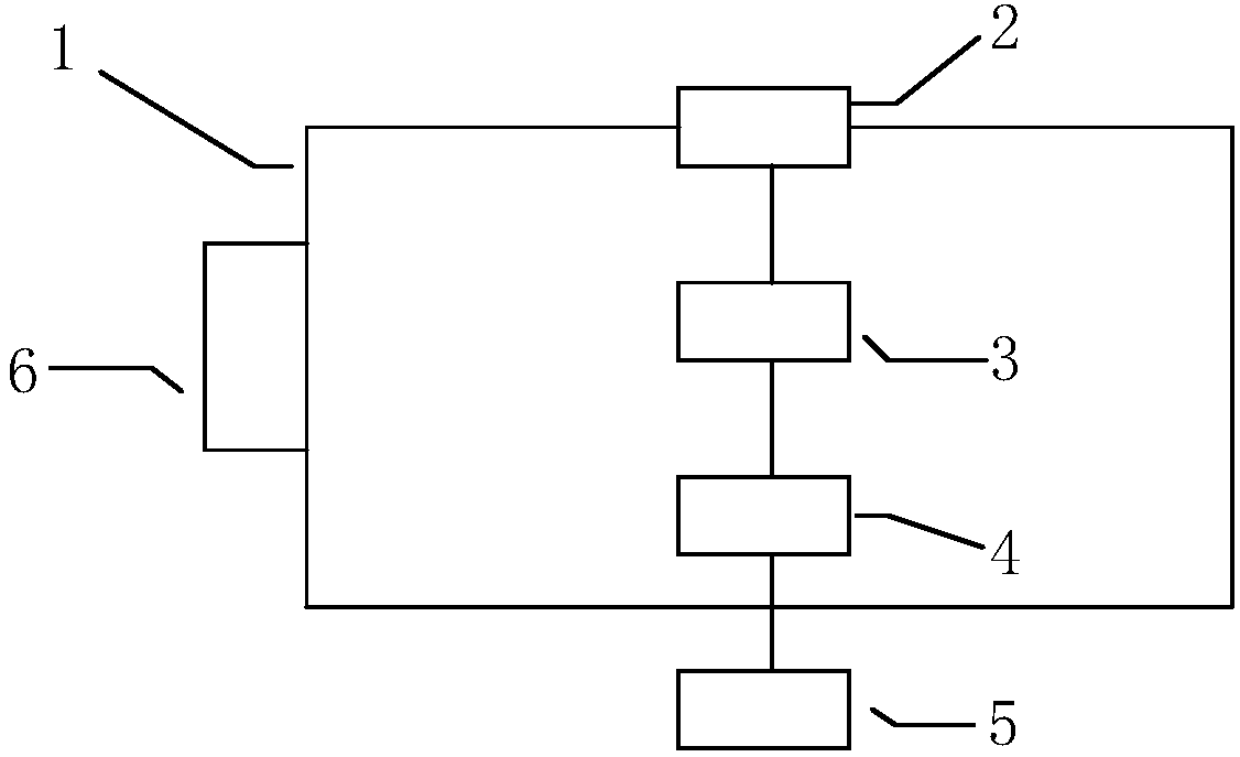
[0032] This embodiment is described with reference to the accompanying drawings. Such as Figure 1-5 As shown, a microparticle forward scattered light detection device includes a platform 1, a microfluidic chip 3, a driving component 6, a light excitation component 2, a light detection component 4 and a data processing component 5, and the platform 1 is a darkroom structure, the light excitation component 2 is embedded on the top of the platform 1, the microfluidic chip 3 and the light detection component 4 are fixed in the platform 1, the light detection component 4 is located under the microfluidic chip 3, and the driving component 6 passes through the platform 1 and the microfluidic control The chip 3 is connected, the light detection component 4 is connected with the data processing component 5, and the PC display terminal 21 is connected with the data processing component 5;
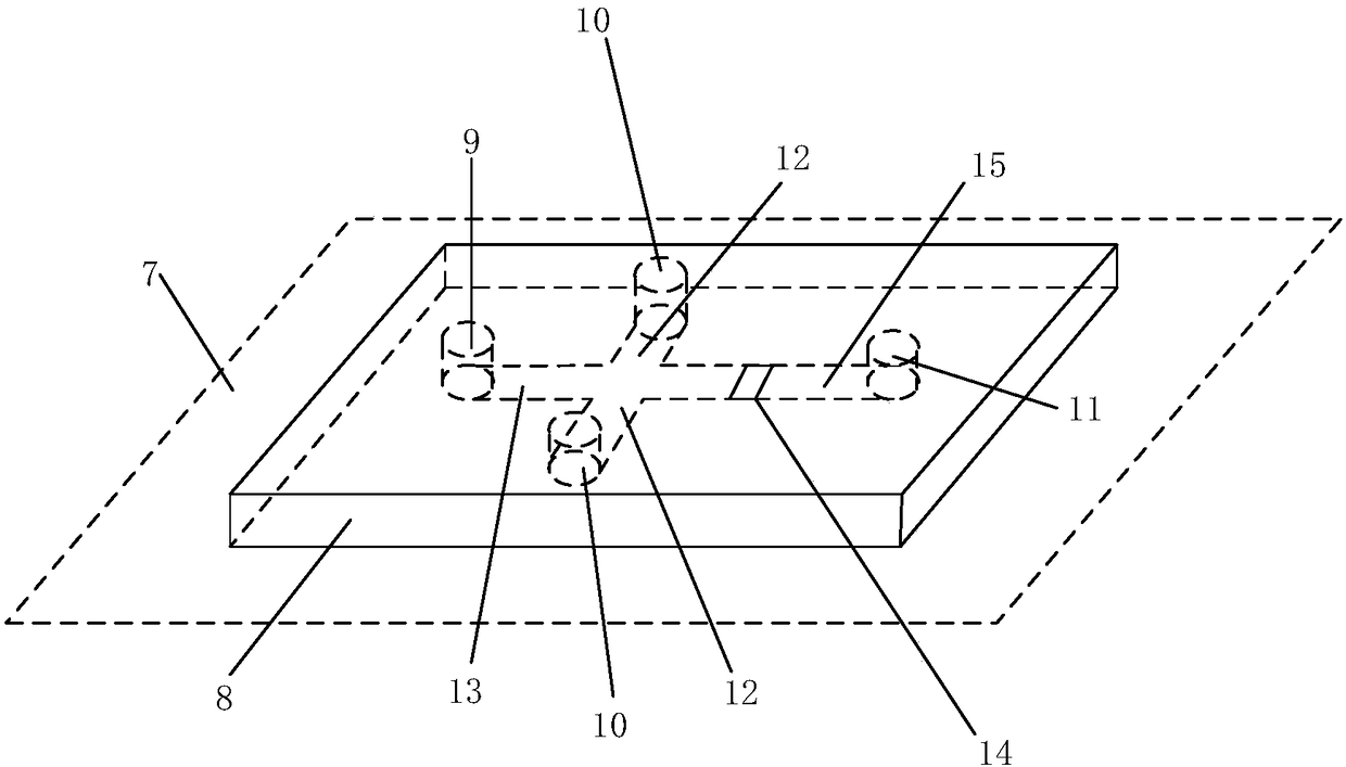
[0033] The microfluidic chip 3 is composed of a glass sheet 7 and polydimethylsiloxane 8 fixed ...
PUM
 Abstract
Description
Claims
Application Information
 - R&D
- Intellectual Property
- Life Sciences
- Materials
- Tech Scout
- Unparalleled Data Quality
- Higher Quality Content
- 60% Fewer Hallucinations
Browse by: Latest US Patents, China's latest patents, Technical Efficacy Thesaurus, Application Domain, Technology Topic, Popular Technical Reports.
© 2025 PatSnap. All rights reserved.Legal|Privacy policy|Modern Slavery Act Transparency Statement|Sitemap|About US| Contact US: help@patsnap.com