

Quasi-zero-expansion space optical remote sensor supporting structure and method thereof
An optical remote sensor and a technology for expanding space, applied in the field of space optical remote sensing, can solve the problems of difficult implementation and high cost, and achieve the effects of improving structural rigidity, low cost and simple structure
- Summary
- Abstract
- Description
- Claims
- Application Information
AI Technical Summary
Problems solved by technology
Method used
Image

Examples
Embodiment 1
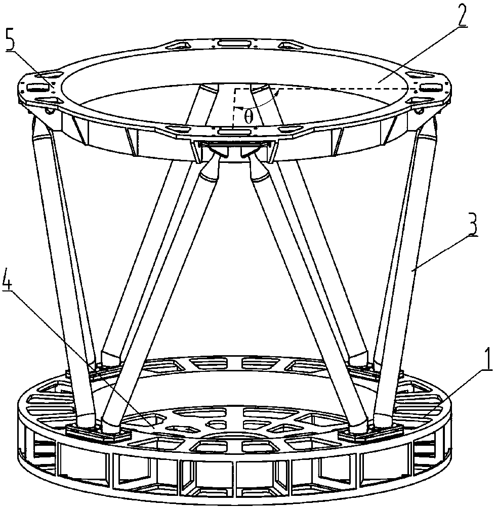
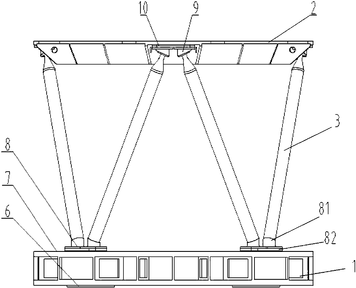
[0049] From figure 1 , figure 2 and image 3 It can be seen that the support structure of the quasi-zero-expansion space optical remote sensor in this embodiment mainly includes a bottom support frame 1, a top support frame 2, and eight support truss rods 3 and 4 between the bottom support frame 1 and the top support frame 2. One set of bottom joints 8 and four sets of top joints 9;
[0050] The bottom joint 8 includes a joint end 81 and a bottom joint installation surface 82, and one bottom joint installation surface 82 is provided with two joint ends 81; Figure 4 It can be seen that the top joint 9 specifically includes a top joint mounting base 15 and two thin neck connectors 13 arranged on the top joint mounting base 15, from Figure 6 It can be seen that the thin neck connector 13 includes a large end 131 and a small end 132, the large end 131 of the thin neck connector 13 is in the shape of a cone, the small end 132 is in the shape of a cylinder, and the diameter of...
Embodiment 2
[0070] Different from Embodiment 1, this embodiment includes n-layer support truss bar units, and also includes ring beams 16 arranged between two adjacent layers of support truss bar units, and the two end faces of the ring beams are provided with The top joint, the two ends of the support truss bar 3 in the first layer support truss bar unit 17 are respectively connected to the ring beam 16 and the bottom support frame 1 through the large end 131 of the thin neck connector 13 and the joint end 81 of the bottom joint 8 Connection; the two ends of the support truss rod 3 in the second layer support truss rod unit 18 to the nth layer support truss rod unit 19 are all fixed on the adjacent two ring beams 16 by the large end 131 of the thin neck connector 13 Between or between the top support frame 2 and the ring beam 16; adjacent support truss rods form a triangular configuration with the bottom support frame, top support frame or ring beam. The ring-shaped beam 16 is also made ...
PUM
 Abstract
Description
Claims
Application Information