MEMS micro vibrating mirror and manufacturing method for prefabricating MEMS micro vibrating mirror based on SOI top silicon

A manufacturing method and technology of micro-galvanometers, which are applied in optical components, optics, instruments, etc., can solve the problems of affecting the torsion angle and performance of the galvanometer, and the large quality of the large-scale mirror structure, so as to shorten the processing time and enhance the electrical power. Isolation effect, the effect of large corners

Active Publication Date: 2018-09-28
XI AN ZHISENSOR TECH CO LTD
View PDF14 Cites 9 Cited by
  • Summary
  • Abstract
  • Description
  • Claims
  • Application Information

AI Technical Summary

Problems solved by technology

[0006] In order to solve the problem that the quality of the large-scale mirror structure of the MEMS micro-vibration mirror processed by the conventional SOI wafer is too large, which affects the torsion angle and performan...

Method used


Image

  • MEMS micro vibrating mirror and manufacturing method for prefabricating MEMS micro vibrating mirror based on SOI top silicon
  • MEMS micro vibrating mirror and manufacturing method for prefabricating MEMS micro vibrating mirror based on SOI top silicon
  • MEMS micro vibrating mirror and manufacturing method for prefabricating MEMS micro vibrating mirror based on SOI top silicon

Examples


Embodiment Construction

[0032] The present invention will be further described below with reference to the accompanying drawings and specific embodiments.

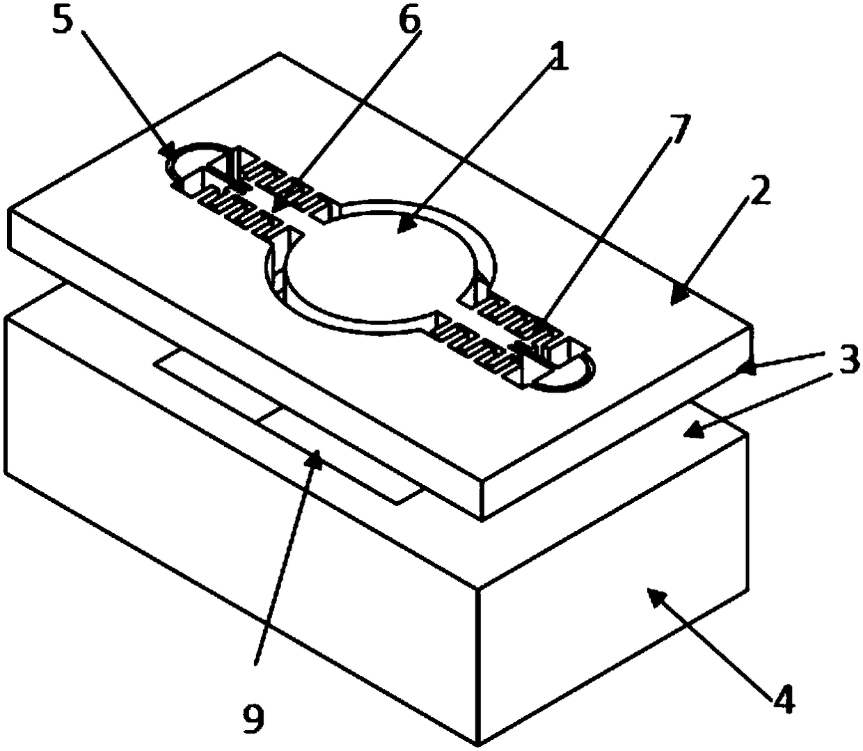
[0033] from figure 2 It can be seen that the MEMS micro-galvo mirror of the present invention includes the bottom layer silicon 4 and the top layer silicon 2 bonded to each other, the movable mirror surface 1, the beam 6, the comb teeth 7, the isolation trench 5 and other structures are located on the top layer silicon, and the movable mirror surface 1 It is connected and fixed by the beam 6, and is isolated by the isolation trench 5, and is independently suspended in the top layer silicon 2. A plurality of first chambers 8 are opened on the back of the movable mirror 1 to reduce the quality of the mirror structure. A second chamber 9 is opened to provide the space required for the movable mirror to twist. The plurality of first chambers 8 are distributed axially symmetrically with respect to the torsion axis of the movable mirror surface, and ...


PUM

PropertyMeasurementUnit
Thicknessaaaaaaaaaa
Thicknessaaaaaaaaaa

Abstract

The invention provides a MEMS micro vibrating mirror and a manufacturing method for prefabricating an MEMS micro vibrating mirror based on SOI top silicon. Before bonding to form an SOI wafer, a specific microstructure is prepared by micromachining on the back side of the top silicon to remove the partial mass of the mirror surface and maintain the structural strength and size of the mirror, meanwhile, a chamber is prepared in advance on the front side of the bottom silicon according to the size of the space required for the torsional motion of the mirror, then the micro-structured sides of the top silicon and the bottom silicon are aligned and bonded to form the SOI wafer and then thin the SOI wafer to the target thickness by the grinding and polishing process, and finally, a metal reflective layer and a mirror movable structure required are processed and manufactured on the front surface of the top silicon, so that the problem of torsional angle and performance of the vibrating mirror due to overlarge mass of the large-sized mirror surface structure of the MEMS micro vibrating mirror processed by the conventional SOI wafer is solved, thereby expanding the degree of freedom of MEMS micro vibrating mirror design and processing, and improving the performance of the MEMS micro vibrating mirror, and being of great significance especially for the fabrication of the MEMS micro vibrating mirror with high reliability and large mirror size.

Description

technical field [0001] The invention relates to the technical field of micro-electromechanical systems, in particular to a MEMS micro-galvanometer and a method for manufacturing the MEMS micro-galvanometer with a specific microstructure prefabricated on the top silicon of an SOI wafer. Background technique [0002] The MEMS micro-galvanometer is a micro-mechanical structure with a movable suspension structure. The electromechanical properties of the micro-structure of each part of the micro-galvanometer determine the performance of the micro-galvanometer. The use of conventional SOI (Silicon-On-Insulator) wafers as the raw material for the structure design and process design of the micro-galvanometer has a significant effect on simplifying the processing technology and improving the processing yield, but there are still shortcomings. During the bulk silicon process of micro-galvanometer mirrors using conventional SOI wafers as raw materials, since the top silicon and the bot...

Claims


Application Information

Patent Timeline
IPC IPC(8): G02B26/08
CPCG02B26/0833
Inventor 游桥明乔大勇夏长锋宋秀敏
Owner XI AN ZHISENSOR TECH CO LTD
Why Eureka
Try Eureka