Supercharge Your Innovation With Domain-Expert AI Agents!

Servo system and its control method based on real-time motion control platform and fpga

A technology of motion control and servo system, applied in the direction of control system, vector control system, motor generator control, etc., can solve the problems of limited control performance, servo drive performance, inability to make full use of controller performance, and inability to achieve satisfactory control effects, etc. , to achieve the effect of shortening the control algorithm cycle, increasing flexibility, and meeting the requirements of high performance

Active Publication Date: 2020-05-12
SHANDONG UNIV
View PDF5 Cites 0 Cited by
  • Summary
  • Abstract
  • Description
  • Claims
  • Application Information

AI Technical Summary

Problems solved by technology

[0003] Most servos on the market use DSP and MCU software solutions. Due to the limitation of hardware chip performance, this kind of control scheme makes the period of the three closed-loop loops of the servo system too large, resulting in the failure to achieve satisfactory control effects in demanding environments.
[0004] As the data processing function of the upper computer becomes more and more powerful, the performance of the motion controller is also more and more powerful. Now the motion controllers on the market basically only run the motion control algorithm and do not involve the three-loop algorithm of the servo drive. In this way, the performance of the controller cannot be fully utilized; at the same time, in the scheme where the motion controller and the servo driver are separated, the algorithm of the servo driver is usually solidified, and the control performance is largely limited by the performance of the servo driver
[0005] In summary, there is still a lack of effective solutions to the problem of how to effectively combine motion controllers and servo drives to achieve high-performance servo drives in the prior art

Method used


Image

  • Servo system and its control method based on real-time motion control platform and fpga
  • Servo system and its control method based on real-time motion control platform and fpga
  • Servo system and its control method based on real-time motion control platform and fpga

Examples


Embodiment 1

[0053] The purpose of Embodiment 1 is to provide the first purpose of the present invention is to provide a servo system based on a real-time motion control platform and FPGA.

[0054] In order to achieve the above object, the present invention adopts the following technical scheme:

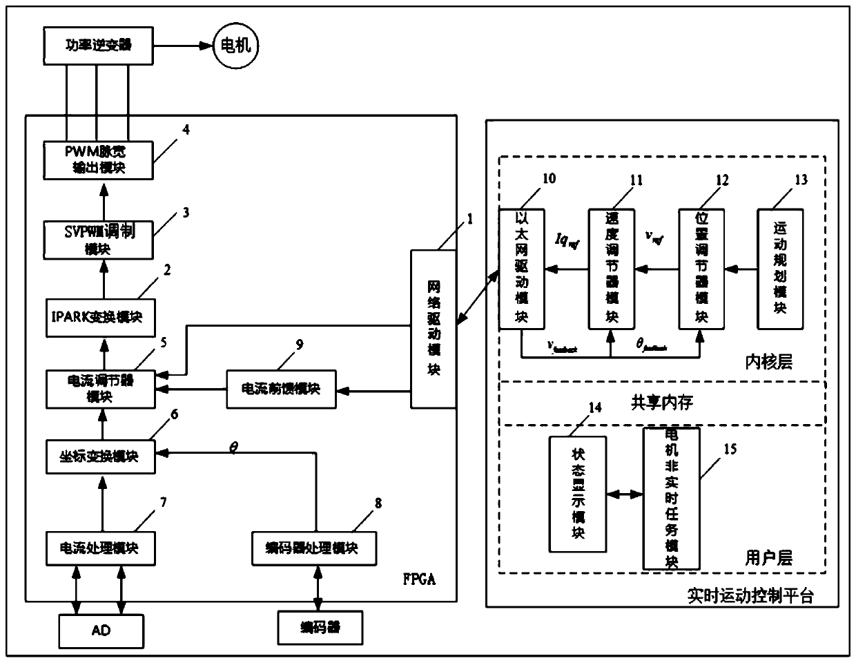
[0055] like figure 1 as shown,

[0056] A servo system based on a real-time motion control platform and an FPGA, the system mainly includes two parts: a real-time motion control platform and an FPGA connected by sequential communication; the real-time motion control platform is configured to run a motion planning algorithm to obtain given position information, The output is transmitted to the industrial Ethernet network through the position regulator and the speed regulator respectively, and the data interaction with the FPGA is performed; the FPGA is configured to receive the current reference vector signal transmitted by the industrial Ethernet, and through the pure hardware logic circuit The...


PUM


Abstract

The invention discloses a servo system based on a real-time motion control platform and FPGA, and a control method thereof. The servo system comprises the real-time motion control platform and the FPGA orderly communicated and connected; the real-time motion control platform is configured to operate a motion planning algorithm to obtain location given information, and output and transmit the location given information to an industrial Ethernet network through a location regulator and a speed regulator, thereby performing data interaction with the FPGA; the FPGA is configured to receive a current reference vector signal transmitted by a network driving module, and produce PWM modulation wave by a current loop through a pure hardware logic circuit so as to drive a power module; and the sampled feedback data is transmitted to the real-time control platform through the industrial Ethernet so as to form a closed loop.

Description

technical field [0001] The invention belongs to the technical field of motion control, and in particular relates to a servo system based on a real-time motion control platform and FPGA and a control method thereof. Background technique [0002] Since the 1980s, with the rapid development of supporting technologies such as power electronics technology, control technology and computer technology, the development of AC servo control technology has made great progress. At present, AC servo technology has become one of the supports of industrial automation. . Among them, the servo control technology is one of the most critical technologies that determine the performance of the servo system. [0003] Most servos on the market use DSP and MCU software solutions. Due to the limitation of hardware chip performance, this kind of control scheme makes the period of the three closed-loop loops of the servo system too large, resulting in the failure to achieve satisfactory control effect...

Claims


Application Information

Patent Timeline
Patent Type & Authority Patents(China)
IPC IPC(8): H02P21/18H02P23/00H02P23/14
CPCH02P21/18H02P23/0077H02P23/14
Inventor 张承瑞王瑜马学斌张振京张文龙张振华
Owner SHANDONG UNIV
Features
  • R&D
  • Intellectual Property
  • Life Sciences
  • Materials
  • Tech Scout
  • Unparalleled Data Quality
  • Higher Quality Content
  • 60% Fewer Hallucinations
Learn More