Material conveying device for ore dressing

A material transmission and conveyor belt technology, which is applied in the field of material transmission devices for mineral processing, can solve problems such as high cost, high energy consumption, and poor performance of material conveying mechanisms, and achieve stable and safe material transfer, low energy consumption, and safety high effect

Inactive Publication Date: 2018-10-02
何征徽
View PDF0 Cites 0 Cited by
  • Summary
  • Abstract
  • Description
  • Claims
  • Application Information

AI Technical Summary

Problems solved by technology

[0002] At present, the application of ore can be seen everywhere. Some ore-related equipment and systems have been born, and the mineral processing technology has been continuously developed. With the vigorous development of the mineral processing industry, the raw materials often need to be crushed in the mineral processing process. Classification and classification refers to the operation of reducing the particle size of mineral raw materials and having certain particle size distribution characteristics through certain mechanical equipment; usually the operation of reducing the particle size to 20-5mm is called crushing, and the corresponding equipment is a crusher; the finer crushing operation is It is called grinding; in this series of operations, a material conveying mechanism is needed to help complete; material mixing and conveying can be seen everywhere; but the existing material conveying mechanism has poor performance and high energy consumption; in actual use, the cost is high No less, so it needs to be improved

Method used


Image

  • Material conveying device for ore dressing
  • Material conveying device for ore dressing
  • Material conveying device for ore dressing

Examples


Embodiment Construction

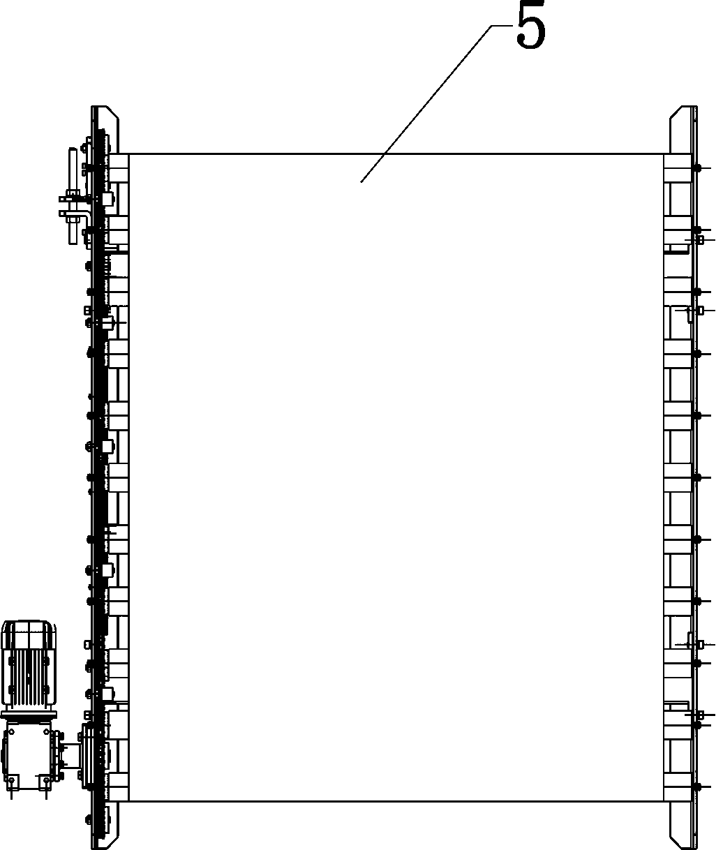
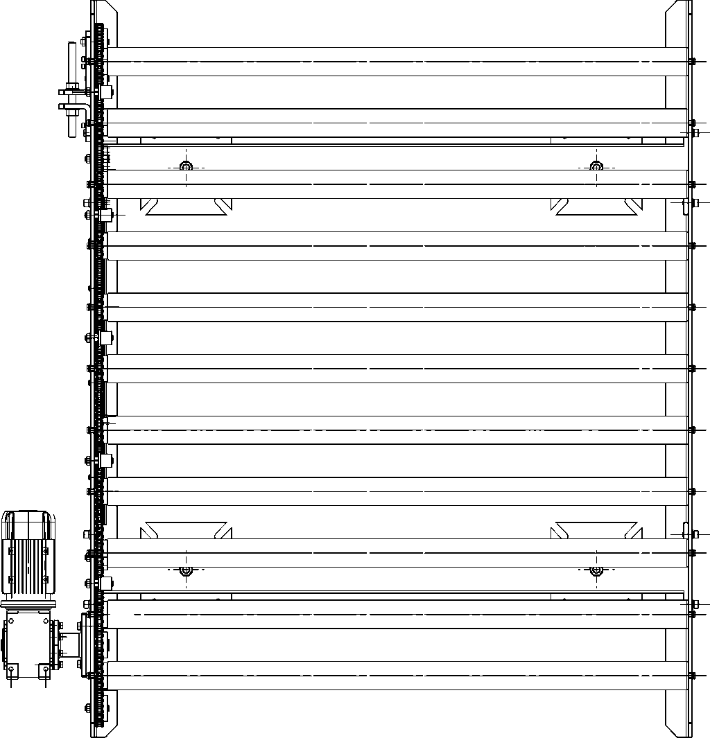
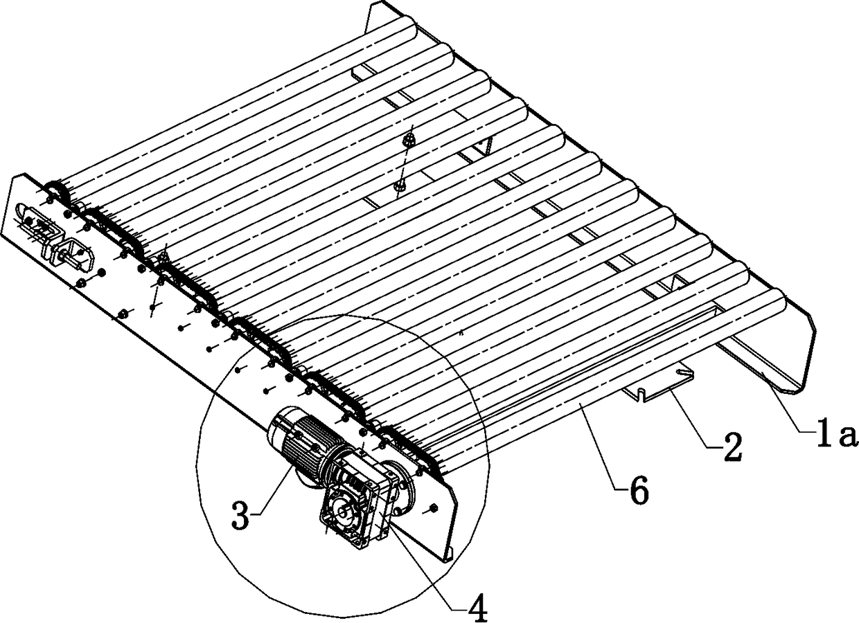
[0011] The following will be combined with Figure 1-7 The present invention is described in detail, and the technical solutions in the embodiments of the present invention are clearly and completely described. Apparently, the described embodiments are only some of the embodiments of the present invention, not all of them. Based on the embodiments of the present invention, all other embodiments obtained by persons of ordinary skill in the art without making creative efforts belong to the protection scope of the present invention.

[0012] The present invention provides a kind of material conveying device for beneficiation through improvement, such as Figure 1-7 As shown, it can be implemented in the following manner; it has frame 1, frame support feet 2, transmission motor 3, transmission box 4 (with worm gear and worm inside), material conveyor belt 5, conveyor belt roller 6, chain 7, chain Pressing wheel 8, chain main rotating gear 9, chain driven gear 10; frame 1 is divid...


PUM


Abstract

The invention discloses a material conveying device for ore dressing. The material conveying device for ore dressing is characterized in that conveying belt rotating rollers capable of rotating are arranged between the left part and the right part of a machine frame, a material conveying belt is arranged on the conveying belt rotating rollers, a chain, a chain pressing wheel, a chain main rotatinggear and a chain driven gear are located on the inner side surface of the machine frame provided with a transmission motor, the transmission motor drives a transmission box to work, the output end ofthe transmission box drives the chain main rotating gear to rotate, and the chain bypasses the conveying belt rotating rollers, the chain pressing wheel, the chain main rotating gear and the chain driven gear. The material conveying device for ore dressing is simple in overall structure, firm in overall structure, and small in occupied area; due to the adoption of roller transmission, the energyconsumption is low, the noise is low, the effect of being wear-resistant is achieved, the material conveying efficiency is high, the structure is simple, the operation is easy, the transmission performance is good, the safety is high, object transferring is stable and safe, and the speed is high; and moreover, compared with a traditional direct-connected electric roller, the material conveying device is easier to maintain and replace, and meanwhile, reduction of the maintenance cost of the material conveying device is facilitated.

Description

technical field [0001] The invention relates to the field of material conveying, in particular to a material conveying device for beneficiation. Background technique [0002] At present, the application of ore can be seen everywhere. Some ore-related equipment and systems have been born, and the mineral processing technology has been continuously developed. With the vigorous development of the mineral processing industry, the raw materials often need to be crushed in the mineral processing process. Classification and classification refers to the operation of reducing the particle size of mineral raw materials and having certain particle size distribution characteristics through certain mechanical equipment; usually the operation of reducing the particle size to 20-5mm is called crushing, and the corresponding equipment is a crusher; the finer crushing operation is It is called grinding; in this series of operations, a material conveying mechanism is needed to help complete; ...

Claims


Application Information

Patent Timeline
IPC IPC(8): B65G17/02
CPCB65G17/02
Inventor 何征徽
Owner 何征徽
Why Eureka
Try Eureka