
Split sandwich heat-insulation wall combined type connecting piece

A technology for thermal insulation walls and connectors, applied in thermal insulation, walls, building components, etc., can solve the problems of increased construction difficulty, inconvenient installation and disassembly, and unsuitable for large-scale laying and installation of building walls.

Inactive Publication Date: 2018-10-02
山东金富地新型建材科技股份有限公司
View PDF10 Cites 4 Cited by
  • Summary
  • Abstract
  • Description
  • Claims
  • Application Information

AI Technical Summary

Problems solved by technology

[0003] The Chinese patent application number is 20162039222205.3, and the patent name is split-type sandwich insulation wall connector. There is a plug on a connecting rod, and the plug is composed of an inner test board, an outer board and a plug board located between the inner and outer boards." Although this patented technology adopts a sandwich installation structure, it is found in actual manufacturing and subsequent installation that The two-stage manufacturing and storage cost of the connector is relatively high, and it is inconvenient to install and disassemble. It is not suitable for large-scale laying and installation of building walls, which will not increase the difficulty of construction and cannot meet the requirements of building insulation walls.

Method used


Image

  • Split sandwich heat-insulation wall combined type connecting piece
  • Split sandwich heat-insulation wall combined type connecting piece
  • Split sandwich heat-insulation wall combined type connecting piece

Examples


Embodiment 1

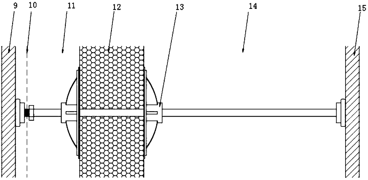
[0023] Combined with the manual figure 1 , figure 2 and image 3 As shown, a split sandwich insulation wall combined connector includes inner and outer cylindrical ends, an inner baffle plate 2, a first steel bar connecting rod 3, an outer clamping disc 4, a second connecting rod 5, an inner clamping The disc 6 and the third connecting rod 7 are composed of; the clamping disc is set as a semicircular pot cover shape, and the inner threaded through hole 13 is installed on the centerline direction of the circular convex surface of the clamping disc, and the connecting piece is installed Connect sequentially from left to right:

[0024] A steel wire mesh 10 is set between the outer cylindrical end 1 and the inner baffle plate 2, and is connected to the threaded rod at the left end of the first connecting rod 3, and the threaded rod at the right end of the first connecting rod 3 is connected to the threaded rod at the right end of the first connecting rod 3. 13 in the inner th...

Embodiment 2

[0026] The inner and outer clamping discs are in the shape of an outer circular terrace, and the connecting rod is set in three sections.

Embodiment 3

[0028] Based on the basis of Examples 1 and 2, the one-stage connecting rod is used for installation of the interior wall insulation, which does not need to hang the wall skin, and the installation is beautiful and fast. Reduce the area of ​​the inner wall.


PUM


Abstract

The invention discloses a split sandwich heat-insulation wall combined type connecting piece comprising cylindrical end heads, an internal clamping disc, an external clamping disc and a three-sectiontype connecting rod. A steel wire mesh is mounted between the external cylindrical end head and an internal baffle, and the external cylindrical end head and the internal baffle are connected to one end of one of the connecting rod bodies, and the other end of each connecting rod body is connected into internal-thread threaded through holes in the center line of the corresponding clamping disc toform an external concrete layer, and an EPS formwork is clamped between the clamping discs; through connection of the connecting rod bodies, the internal clamping disc is connected with the external cylindrical end head through the connecting rod bodies, an internal concrete layer is formed between the internal clamping disc and the external cylindrical end head, and the whole connecting piece isfixed to an inner side formwork through the internal cylindrical end head and the external cylindrical end head. The split sandwich heat-insulation wall combined type connecting piece is simple in structure, convenient and fast in dismounting and mounting, firm in suspending, and low in manufacturing cost.

Description

technical field [0001] The invention relates to the technical field of assembled wall connecting members of large thermal insulation boards in the construction industry, in particular to a split sandwich thermal insulation wall combined connector. Background technique [0002] At present, EPS insulation boards are used as insulation walls in the construction industry, and at the same time, the EPS insulation board layer is placed between two layers of reinforced concrete to form a sandwich insulation wall structure. [0003] The Chinese patent application number is 20162039222205.3, and the patent name is split-type sandwich insulation wall connector. There is a plug on a connecting rod, and the plug is composed of an inner test board, an outer board and a plug board located between the inner and outer boards." Although this patented technology adopts a sandwich installation structure, it is found in actual manufacturing and subsequent installation that The two-stage manufa...

Claims


Application Information

Patent Timeline
IPC IPC(8): E04B2/00E04B1/76
CPCE04B2/00E04B1/7608
Inventor 卜志宏
Owner 山东金富地新型建材科技股份有限公司
Learn More