A kind of multi-stage fluidized bed biological deodorization device and process method
A biological deodorization and fluidized bed technology, which is applied in separation methods, chemical instruments and methods, and separation of dispersed particles, can solve the problems of small footprint and microbial film plugging fillers, and achieve small footprint and improved utilization efficiency, improve the effect of deodorization effect
- Summary
- Abstract
- Description
- Claims
- Application Information
AI Technical Summary
Problems solved by technology
Method used
Image
Examples
Embodiment 1
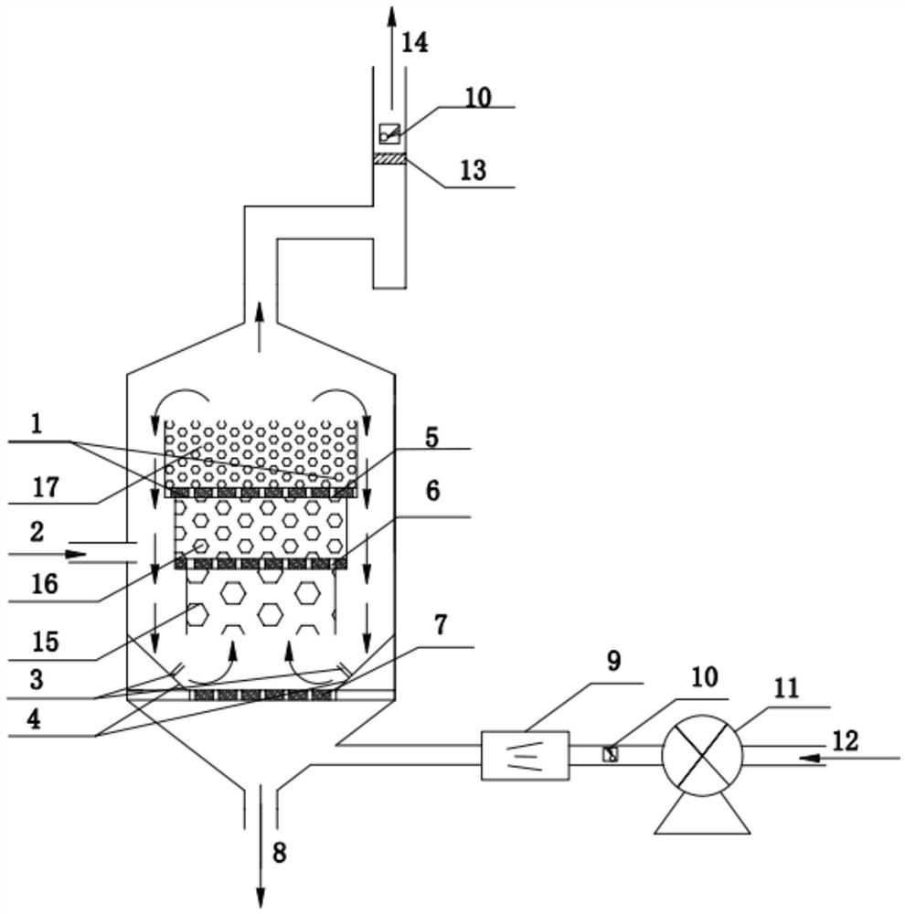
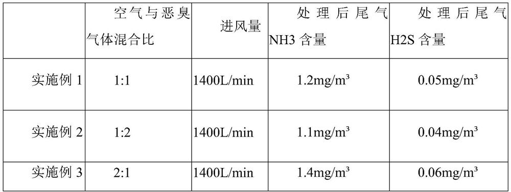
[0054] When the device is started, the biological filter material with a particle size of 40mm is input into the device through the feed port 2, and reaches the top of the 20mm aperture sieve plate 7 through the circulation channel and the annular deflector 4; The malodorous gas is input into the reactor by the fan 11 with an air volume of 1400 L / min, and is mixed with the water vapor ejected from the humidifier 9 at the same time. The mixed gas enters the reactor through the air inlet 12, and the 20mm aperture sieve plate 7 redistributes the mixed gas. The upward air resistance is given to the biological filter material. At the same time, the gas ejected from the nozzle 3 forms a spin flow in the reactor, and the biological filter material is driven by the gas to form a fluidized state. The first-level reaction chamber 15 reacts, and at this time the malodorous gas can be initially removed; as the reaction progresses, the filter material is gradually consumed, and the particle...
Embodiment 2
[0056] When the device is started, the biological filter material with a particle size of 40mm is input into the device through the feed port 2, and reaches the top of the 20mm aperture sieve plate 7 through the circulation channel and the annular guide plate 4; the air mixed with the ratio of 1:2 and The malodorous gas is input into the reactor by the fan 11 with an air volume of 1400 L / min, and is mixed with the water vapor ejected from the humidifier 9 at the same time. The mixed gas enters the reactor through the air inlet 12, and the 20mm aperture sieve plate 7 redistributes the mixed gas. The upward air resistance is given to the biological filter material. At the same time, the gas ejected from the nozzle 3 forms a spin flow in the reactor, and the biological filter material is driven by the gas to form a fluidized state. The first-level reaction chamber 15 reacts, and at this time the malodorous gas can be initially removed; as the reaction progresses, the filter materi...
Embodiment 3
[0058] When starting the device, the biological filter material with a particle size of 40mm is input into the device through the feed port 2, and reaches the top of the 20mm aperture sieve plate 7 through the circulation channel and the annular deflector 4; the air mixed with the ratio of 2:1 and The malodorous gas is input into the reactor by the fan 11 with an air volume of 1400 L / min, and is mixed with the water vapor ejected from the humidifier 9 at the same time. The mixed gas enters the reactor through the air inlet 12, and the 20mm aperture sieve plate 7 redistributes the mixed gas. The upward air resistance is given to the biological filter material. At the same time, the gas ejected from the nozzle 3 forms a spin flow in the reactor, and the biological filter material is driven by the gas to form a fluidized state. The first-level reaction chamber 15 reacts, and at this time the malodorous gas can be initially removed; as the reaction progresses, the filter material i...
PUM
| Property | Measurement | Unit |
|---|---|---|
| Mesh diameter | aaaaa | aaaaa |
| Mesh diameter | aaaaa | aaaaa |
| Mesh diameter | aaaaa | aaaaa |
Abstract
Description
Claims
Application Information
 - R&D Engineer
- R&D Manager
- IP Professional
- Industry Leading Data Capabilities
- Powerful AI technology
- Patent DNA Extraction
Browse by: Latest US Patents, China's latest patents, Technical Efficacy Thesaurus, Application Domain, Technology Topic, Popular Technical Reports.
© 2024 PatSnap. All rights reserved.Legal|Privacy policy|Modern Slavery Act Transparency Statement|Sitemap|About US| Contact US: help@patsnap.com


