Multifunctional rotary displacement conveying mechanical arm capable of taking materials in branched mode

A technology of rotating, shifting and conveying machinery, applied in the field of robotic arms, can solve the problems of not being able to meet the production needs of multiple varieties and small batches, low conveying efficiency, and increased equipment investment costs

Pending Publication Date: 2018-10-09
薛敏强
View PDF6 Cites 35 Cited by
  • Summary
  • Abstract
  • Description
  • Claims
  • Application Information

AI Technical Summary

Problems solved by technology

However, the existing manipulators can only grab items of the same specification for delivery. For the delivery of products of different specifications, different manipulators need to be matched, which increases the investment cost of equipment, and the delivery efficiency is low, which cannot meet the production needs of multiple varieties and small batches.

Method used


Image

  • Multifunctional rotary displacement conveying mechanical arm capable of taking materials in branched mode
  • Multifunctional rotary displacement conveying mechanical arm capable of taking materials in branched mode
  • Multifunctional rotary displacement conveying mechanical arm capable of taking materials in branched mode

Examples


Embodiment 1

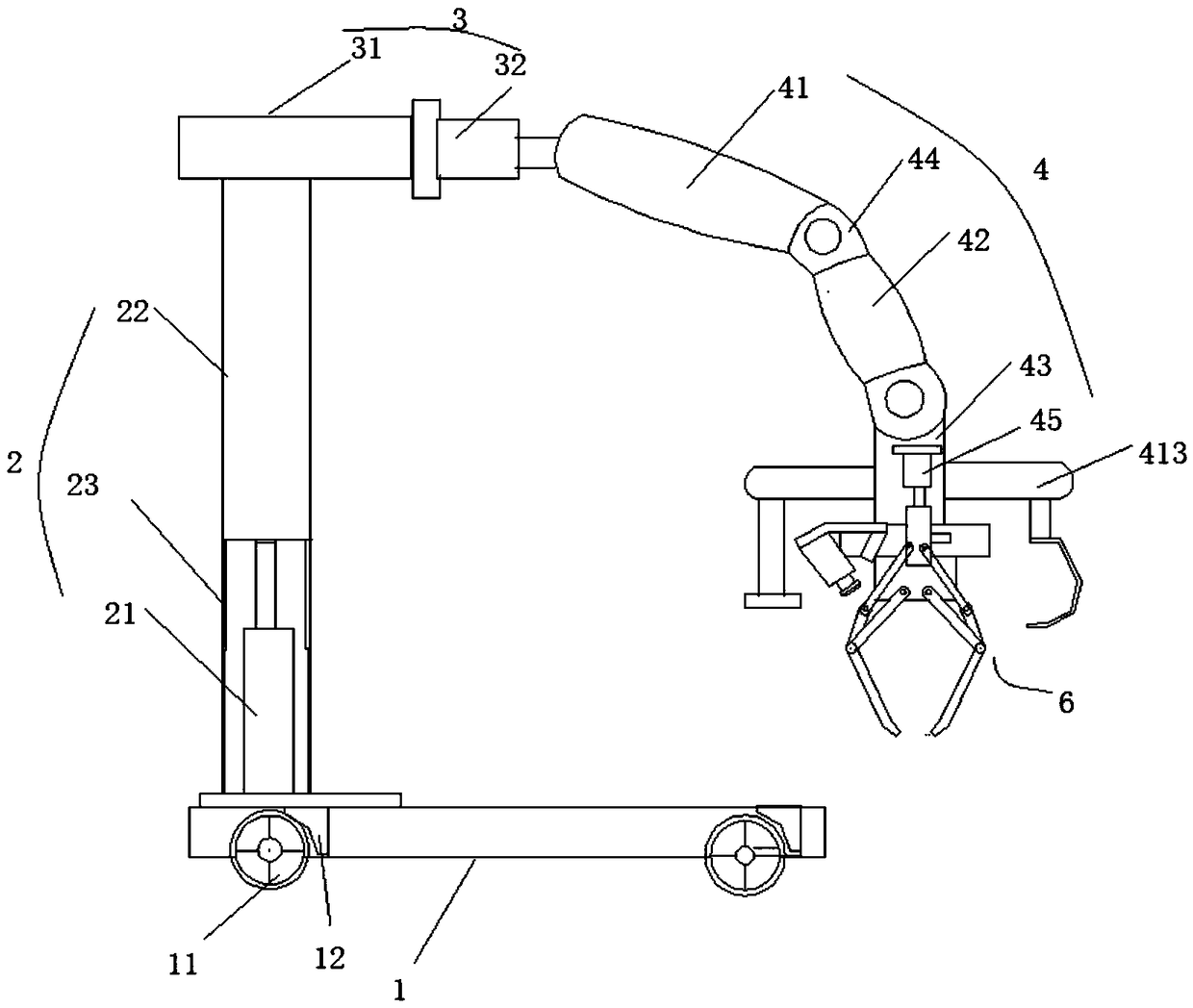
[0100] Such as figure 1 The shown a kind of conveying mechanical arm capable of branching and taking materials with multifunctional rotation and displacement includes a base 1, a lifting column 2, a traverse mechanism 3, a mechanical arm 4, a connecting piece 5 and a mechanical claw 6, and the lifting column 2 The rotating disk 7 is fixed on the base 1, and the traversing mechanism 3 is arranged on the lifting column 2. The lifting column 2 includes a lifting cylinder 21 and a supporting column 22. The bottom of the lifting cylinder 21 is arranged on the rotating disk 7. The moving mechanism 3 is a horizontal cylinder 31 and a beam 32, the beam 32 is connected with the piston rod of the lifting cylinder 21, the horizontal cylinder 31 is arranged on the beam 32, and the piston rod of the horizontal cylinder 31 is connected with the mechanical arm 4; The arm 4 is provided with a plurality of spherical annular holes 411, and a spherical fixed ring 412 is installed in the spherica...

Embodiment 2

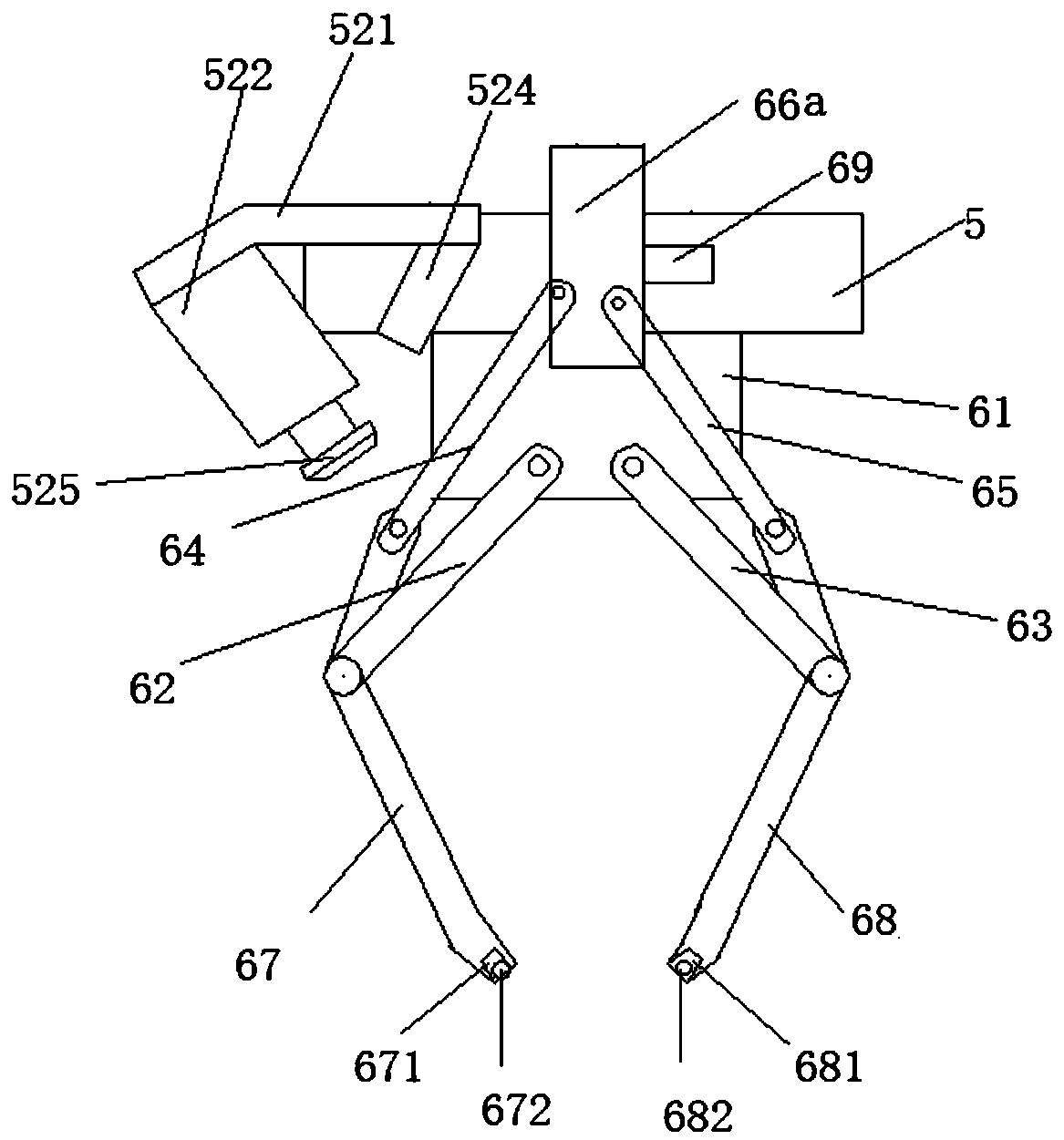
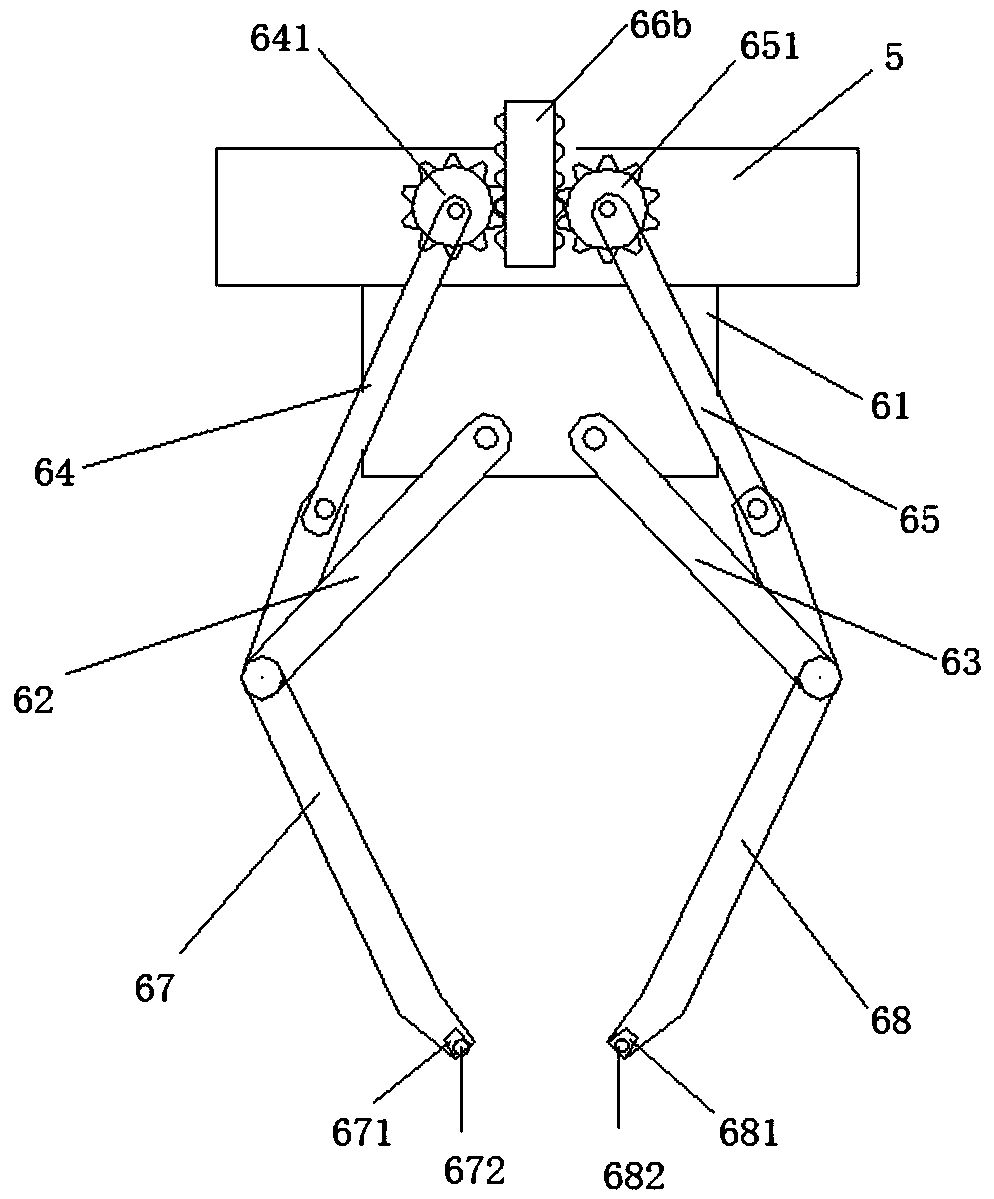
[0102] Such as figure 1 , 4 , 5, 6 and 7 shows a multi-functional rotating and shifting conveying robot arm capable of branching and retrieving materials, including a base 1, a lifting column 2, a lateral movement mechanism 3, a robot arm 4, a connecting piece 5 and a mechanical claw 6 , the lifting column 2 is fixed on the base 1 through the rotating disc 7, the traversing mechanism 3 is arranged on the lifting column 2, and the lifting column 2 includes a lifting cylinder 21 and a supporting column 22, and the bottom of the lifting cylinder 21 is arranged on a rotating On the disk 7, the traverse mechanism 3 is a transverse cylinder 31 and a beam 32, the beam 32 is connected with the piston rod of the lift cylinder 21, the transverse cylinder 31 is arranged on the beam 32, the piston rod of the transverse cylinder 31 is connected to the mechanical arm 4 connection; The mechanical arm 4 is provided with a plurality of spherical ring holes 411, a spherical fixing ring 412 is ...

Embodiment 3

[0112] Such as figure 1 , 4 , 5, 6 and 7 shows a multi-functional rotating and shifting conveying robot arm capable of branching and retrieving materials, including a base 1, a lifting column 2, a lateral movement mechanism 3, a robot arm 4, a connecting piece 5 and a mechanical claw 6 , the lifting column 2 is fixed on the base 1 through the rotating disc 7, the traversing mechanism 3 is arranged on the lifting column 2, and the lifting column 2 includes a lifting cylinder 21 and a supporting column 22, and the bottom of the lifting cylinder 21 is arranged on a rotating On the disk 7, the traverse mechanism 3 is a transverse cylinder 31 and a beam 32, the beam 32 is connected with the piston rod of the lift cylinder 21, the transverse cylinder 31 is arranged on the beam 32, the piston rod of the transverse cylinder 31 is connected to the mechanical arm 4 connection; The mechanical arm 4 is provided with a plurality of spherical ring holes 411, a spherical fixing ring 412 is ...


PUM


Abstract

The invention discloses a multifunctional rotary displacement conveying mechanical arm capable of taking materials in a branched mode. The multifunctional rotary displacement conveying mechanical armcomprises a base, a lifting stand column, a transverse moving mechanism, a mechanical arm body, a connecting piece and a mechanical claw; the lifting stand column is fixed on the base through a rotarydisc, the transverse moving mechanism is arranged on the lifting stand column, the lifting stand column comprises a lifting air cylinder and a supporting stand column, and the bottom of the lifting air cylinder is arranged on the rotary disc; a plurality of spherical ring holes are formed in the mechanical arm body, spherical fixing rings are installed in the spherical ring holes, a branch mechanical arm body penetrates through the spherical annular holes of the mechanical arm body and is fixed on the mechanical arm body, two symmetric arc-shaped notches are formed in each spherical ring hole, the width of the arc-shaped notches is smaller than the width of the spherical fixing rings, and a hook or a vacuum sucking disc is arranged on the branch mechanical arm body. According to the mechanical arm, the branch mechanical arm body is fixed on the mechanical arm body through spherical positioning rings, multi-direction and multi-angle position adjustment of the branch mechanical arm bodyis realized along with the rotation of the spherical positioning rings, and the production requirements of multi-variety small-batch production are met.

Description

technical field [0001] The invention relates to the technical field of mechanical arms, in particular to a multi-functional rotating and shifting conveying mechanical arm capable of branching and retrieving materials. Background technique [0002] With the rapid development of modern industry, industrial equipment is becoming more and more intelligent and efficient. A large number of mechanical arm devices are used in some assembly line operations. The mechanical arm devices are high-precision mechanical claws, which are used for mass production and can improve Productivity. It can be widely used in dispensing, parts placement, screw locking, circuit cutting, etc., and has a wide range of applications. As robotic equipment is more and more widely used in industrial production, various types of robotic equipment have emerged as the times require. In the flexible manufacturing automation production line of medium and small batch production, it is often necessary to realize th...

Claims


Application Information

Patent Timeline
Patent Type & Authority Applications(China)
IPC IPC(8): B25J5/00B25J13/08B25J15/00B25J19/02
CPCB25J5/007B25J13/086B25J15/0057B25J19/026
Inventor 薛敏强
Owner 薛敏强
Why Eureka
Try Eureka