
Rotation-driven charge structure for combined laser chemical propulsion

A technology of rotary drive and thruster, which is applied in the direction of jet propulsion devices, machines/engines, rocket engine devices, etc. It can solve the problems of complex structure and heavy weight of the engine, achieve light weight, high space utilization rate, and increase the amount of charge Effect

Active Publication Date: 2020-01-31
SHANGHAI XINLI POWER EQUIP RES INST
View PDF11 Cites 0 Cited by
  • Summary
  • Abstract
  • Description
  • Claims
  • Application Information

AI Technical Summary

Problems solved by technology

In order to drive the liquid propellant, the laser propulsion engine contains a pressurized structure, resulting in a complex structure and heavy weight of the propulsion engine, which is not suitable for microsatellites

Method used


Image

  • Rotation-driven charge structure for combined laser chemical propulsion
  • Rotation-driven charge structure for combined laser chemical propulsion
  • Rotation-driven charge structure for combined laser chemical propulsion

Examples


Embodiment Construction

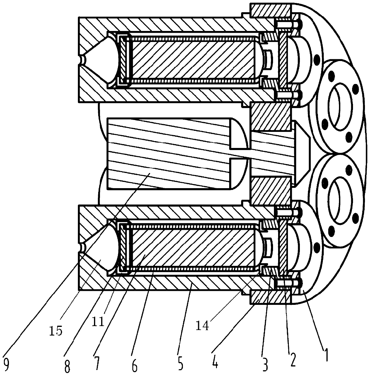
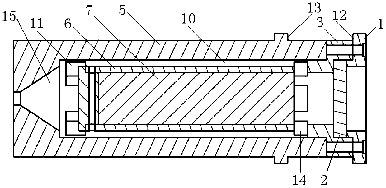
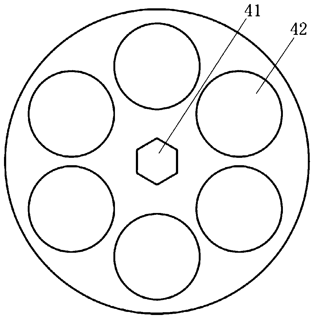
[0026] The following will combine Figure 1 to Figure 4 A further detailed description will be made on the rotation-driven charge structure used in the combined laser chemical thruster of the present invention.

[0027] figure 1 Shown is a cross-sectional view of a rotary-driven charge structure for a combined laser chemical thruster according to a preferred embodiment of the present invention; figure 2 Shown is a cross-sectional view of a single combustion chamber in a preferred embodiment of the present invention.

[0028] see figure 1 and figure 2 , the rotary-driven charge structure for the combined laser chemical thruster of this embodiment includes a turntable 4, a rotary steering gear 9 and at least two combustion chambers;

[0029] The rotary steering gear 9 is connected to the turntable 4, and the rotary steering gear 9 is used to drive the turntable 4 to rotate;

[0030] The combustion chamber is sealed and fixedly connected with the turntable 4, and the rotat...


PUM


Abstract

The invention relates to a rotary driving loading structure for a laser chemical combined propeller. The structure comprises a rotary disc, a rotary steering engine and at least two combustion rooms,wherein the rotary steering engine is connected to the rotary disc and is used for driving the rotary disc to rotate; the combustion rooms are hermetically and fixedly connected to the rotary disc, and the rotary disc rotates to drive the combustion rooms to rotate; each of the combustion rooms is provided with a solid propellant; and the combustion rooms are arranged in parallel, and the rotary steering engine is arranged parallel to the combustion rooms. The rotary driving loading structure for the laser chemical combined propeller provided by the invention is small in size and light in weight, and can meet the power demand on micro satellite orbit control.

Description

technical field [0001] The invention relates to a laser solid micro-thruster, in particular to a rotary-driven charging structure for a combined laser chemical thruster. Background technique [0002] The propulsion system of the existing microsatellites is limited by the size and weight of the satellite, and its charge is low, resulting in the total thrust of the thruster being too low, so that the satellite cannot make a large orbital deviation and maneuver, and its orbit changing function is seriously affected. limit. Increasing the charge amount of the micro-satellite propulsion system will significantly improve the performance of micro-satellites in all aspects, making it easy for micro-satellites to ensure formation flight and complete various tasks. However, the traditional propulsion system is relatively large in size and mass, which is not suitable for the use of microsatellites. [0003] The laser propulsion engine disclosed in patent CN102062019A is a liquid rock...

Claims


Application Information

Patent Timeline
Patent Type & Authority Patents(China)
IPC IPC(8): F02K9/08F02K9/24F02K9/34F02K9/95
CPCF02K9/08F02K9/24F02K9/34F02K9/95
Inventor 华佐豪郭宁周文渊马新建单友辉罗思璇陈伟康赵培莉
Owner SHANGHAI XINLI POWER EQUIP RES INST
Learn More