
Three-valued signal generation device and three-valued signal generation method

A signal generation, ternary technology, applied in the direction of synchronization device, measurement device, logic circuit interface device, etc., can solve the problem of unable to obtain intermediate value, LFPS signal does not follow false signal, increase the total cost and so on

Active Publication Date: 2018-10-09
ANRITSU CORP
View PDF8 Cites 1 Cited by
  • Summary
  • Abstract
  • Description
  • Claims
  • Application Information

AI Technical Summary

Problems solved by technology

[0006] However, the LFPS signal based on the binary NRZ signal is a pseudo signal that does not comply with the USB3.0 / 3.1 standard, and has the following problems: the intermediate value between the high level and the low level cannot be obtained, and it will not become a 3.1 Ternary signal based on high level, middle value level and low level specified in the standard
Furthermore, if the ternary LFPS signal specified in the USB3.0 / 3.1 standard is generated from the binary NRZ signal, there will be a problem that a transient due to AC coupling between input and output specified in the USB3.0 / 3.1 standard will be generated. State response, and a deviation occurs in the common-mode voltage between the differential signals depending on the burst interval and mode, and a problem occurs in the receiving part of the USB device or the host as the object under test, and the signal cannot be received normally.
However, when two signals are combined using a two-channel pattern generator, glitch noise (whisker-like pulses) may be generated due to the phase difference between the two signals, and offsetting for matching the phases of the two signals is required. Slant adjustment (equal length wiring)
In addition, in order to match the phases of the two signals, for example, it is necessary to check the waveform using a waveform observer such as an oscilloscope, which has a problem of increasing the workload of the user.
In addition, in order to synthesize signals, an expensive two-channel pattern generator is indispensable, and there is a problem that the total cost increases accordingly.

Method used


Image

  • Three-valued signal generation device and three-valued signal generation method
  • Three-valued signal generation device and three-valued signal generation method
  • Three-valued signal generation device and three-valued signal generation method

Examples


Embodiment Construction

[0032] Hereinafter, modes for implementing the present invention will be described in detail with reference to the drawings.

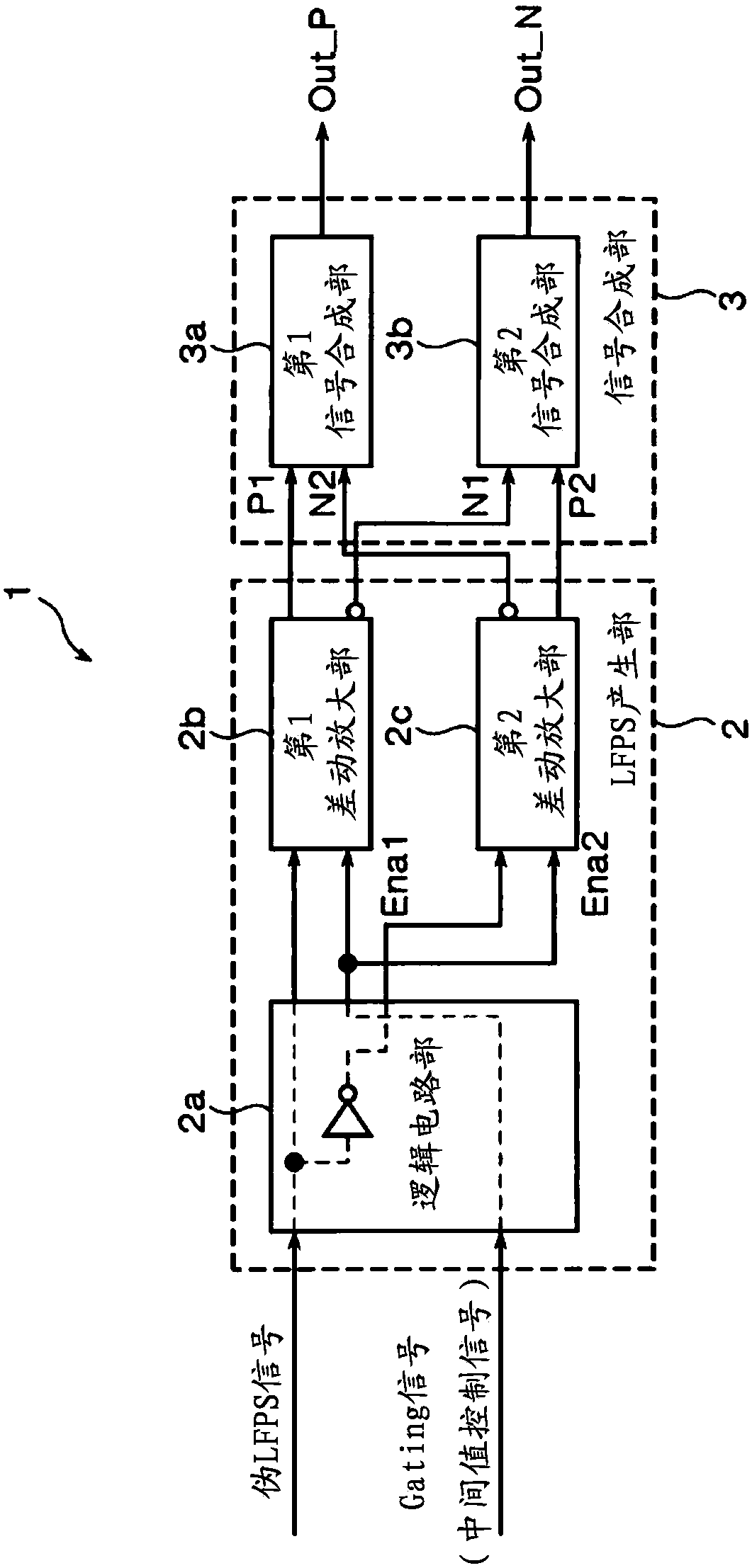
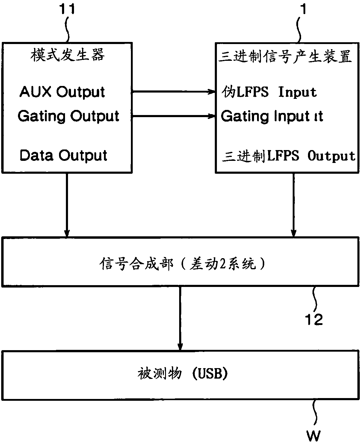
[0033] The present invention relates to a method for generating a USB3.0 / 3.1 standard by using the binary NRZ signal output of AUX Output (pseudo LFPS signal output) and Gating Output (intermediate value control signal output) generated by a 1-channel pattern generator. A ternary signal generating device and a ternary signal generating method for ternary LFPS signals (low-frequency pulse train signals) of low level, high level, and intermediate level.

[0034]In addition, the pattern generator is equipped with an AUX output, and can output a frequency-divided clock synchronized with the bit rate or a timing signal synchronized with the period of the pulse pattern length. AUX Output generates signals by, for example, programmable logic. In the present invention, pseudo LFPS signals are generated and output.

[0035] Furthermore, the pattern generator i...


PUM


Abstract

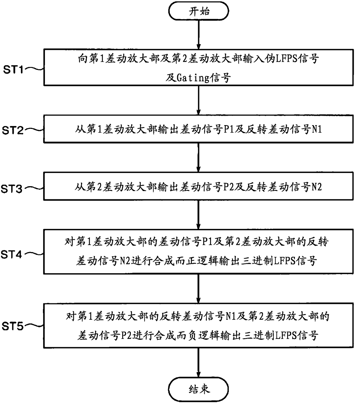
A three-valued signal generation device (1) includes a first differential amplifier (2b) that outputs a differential signal, a second differential amplifier (2c) that outputs a differential signal andan inverted differential signal in accordance with a level based on a reference voltage of an inverted pseudo LFPS signal, which is obtained by inverting a logic level of the pseudo LFPS signal, a first signal synthesis unit (3a) that synthesizes the differential signal from the first differential amplifier (2b) and the inverted differential signal from the second differential amplifier (2c) to perform positive logic output of a three-valued LFPS signal, and a second signal synthesis unit (3b) that synthesizes the inverted differential signal from the first differential amplifier (2b) and thedifferential signal from the second differential amplifier (2c) to perform negative logic output of the three-valued LFPS signal.

Description

technical field [0001] The present invention relates to a ternary signal generating device and a ternary signal generating device for generating a ternary signal of an LFPS (Low Frequency Periodic Signaling: Low Frequency Periodic Signal) signal specified in the Universal Serial Bus (hereinafter referred to as USB) 3.0 / 3.1 standard. Hexadecimal signal generation method. Background technique [0002] Conventionally, when a desired digital communication device is used as a test object and a bit error rate in the test object is measured, for example, a bit error rate measuring device disclosed in Patent Document 1 below is used. In this bit error rate measuring device, in order to determine to what extent the object under test can tolerate electrical stress, an electrical stress signal of a known pattern is applied from the pattern generator as a test signal, and the test signal is sent back inside or outside the object under test. The signal is received by the error detector,...

Claims


Application Information

Patent Timeline
Patent Type & Authority Applications(China)
IPC IPC(8): G06F13/42H03K19/0175G01R31/317
CPCG01R31/3171G06F13/4282H03K19/017509G06F2213/0042H04L25/0272H04L25/4923H04L25/4917H04L7/027H04L25/0276G06F13/40
Inventor 山根一浩
Owner ANRITSU CORP
Learn More