
Delayed coking venting tower spraying system

A spray system and delayed coking technology, which is applied in the field of delayed coking vent tower spray system, can solve problems such as single use, poor quality of return medium, affecting production safety and environmental protection of delayed coking unit

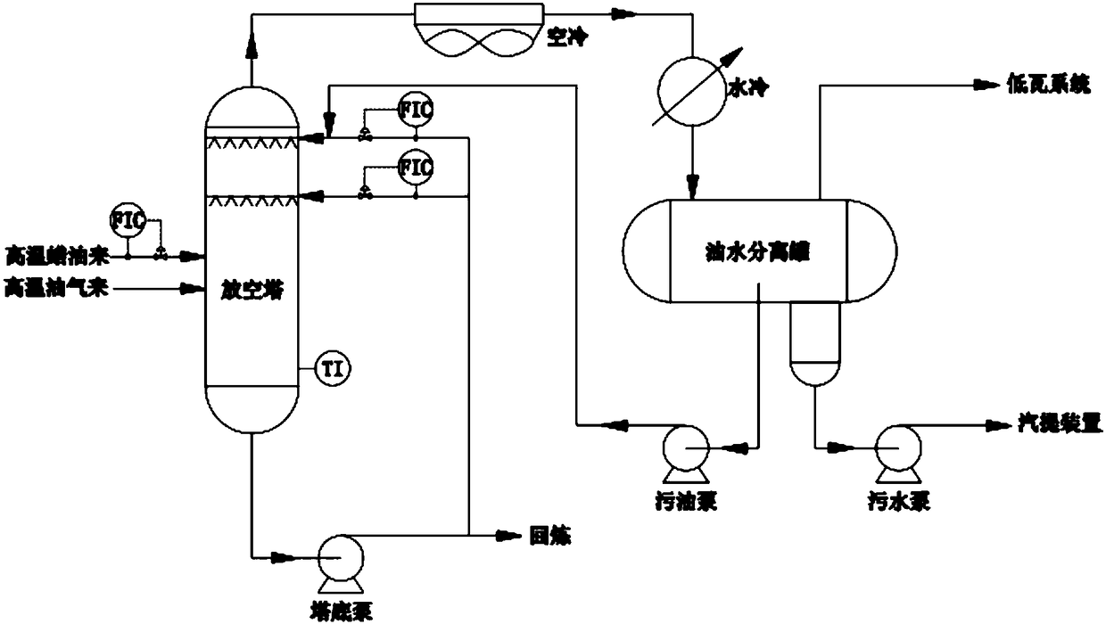
Pending Publication Date: 2018-10-12
董国良
View PDF6 Cites 1 Cited by
  • Summary
  • Abstract
  • Description
  • Claims
  • Application Information

AI Technical Summary

Problems solved by technology

[0004] The delayed coking units of domestic oil refineries basically adopt the traditional vent tower system process. The tower is a multi-layer sieve plate tray, and the top of the tower is refluxed with dirty oil after washing. Reverse contact cooling between the trays, due to the poor properties and high viscosity of the reflux medium, the distribution pipe is generally used to enter the vent tower. The heavy components and coke powder in the reflux are easily carried to the top system by high-temperature oil and gas, and finally enter the top oil-water separation In the tank, resulting in unclear separation of oil and water
The traditional venting tower system has a single purpose, and its operating characteristics are interstitial operations with the coke tower system. After the coke tower cooling is completed, the venting tower system also loses heat, and condensed water is easy to accumulate at the bottom of the tower. The condensed water at the bottom of the tower is vaporized, and the pump at the bottom of the tower is evacuated, which poses a safety hazard
The traditional venting tower system generally has problems such as easy pumping of the tower pump, unclear separation of oil and water in the oil-water liquid tank at the top of the tower, difficulty in refining waste oil, and direct discharge of tail gas to the flare, which seriously affects the safety and environmental protection of delayed coking unit production.

Method used


Image

  • Delayed coking venting tower spraying system
  • Delayed coking venting tower spraying system
  • Delayed coking venting tower spraying system

Examples


Embodiment Construction

[0017] In order to make the objectives, technical solutions and advantages of the present invention clearer, the present invention will be described in further detail below with reference to the embodiments and accompanying drawings.

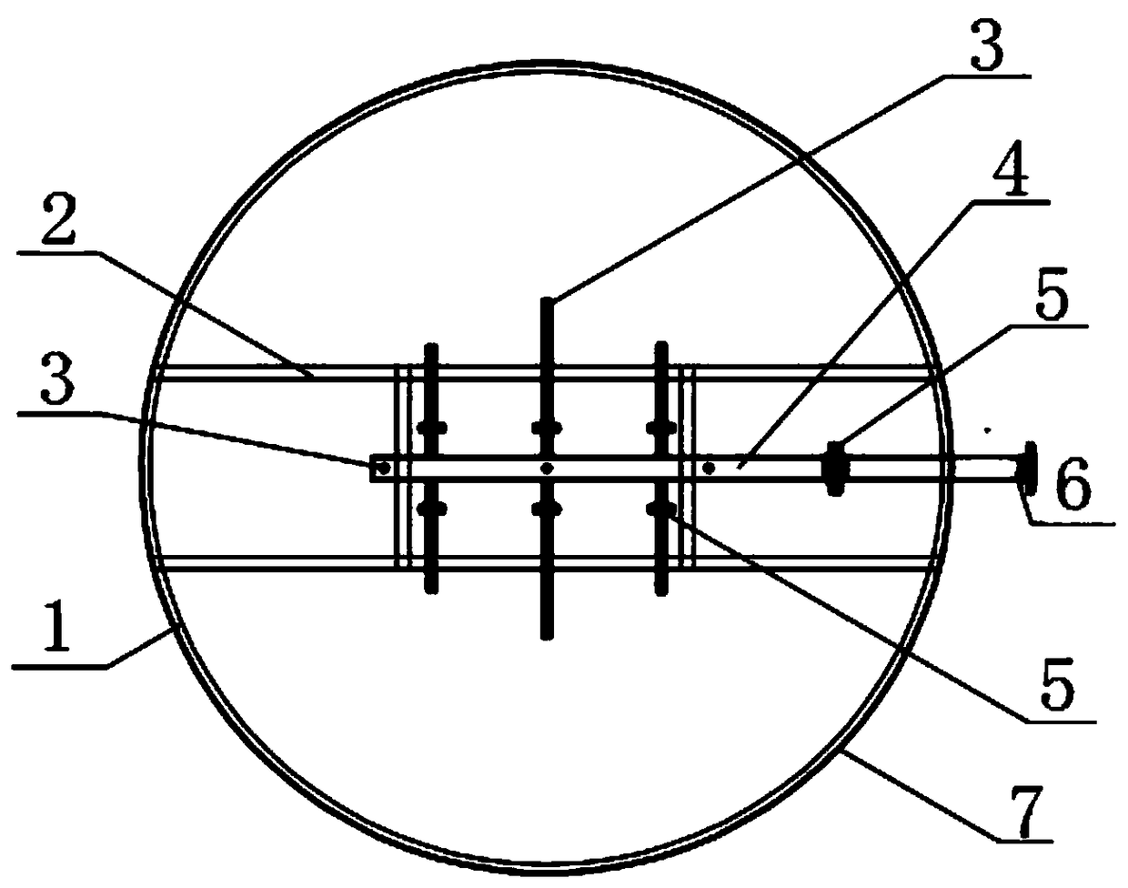
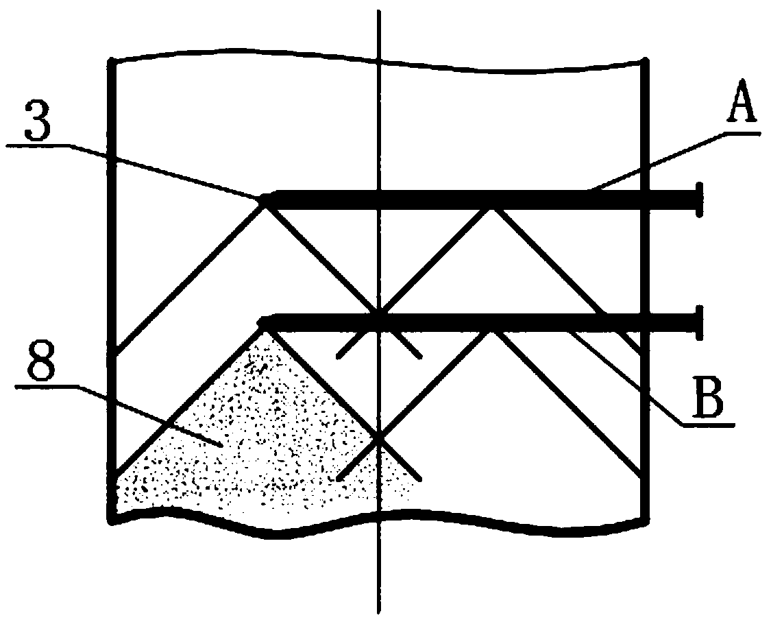
[0018] like figure 1 As shown, it is the top view structure of the spray device of the delayed coking vent tower. The spray device is divided into upper and lower layers and is distributed in the delayed coking vent tower; the spray device includes: a tower body support ring 1, a fixed beam 2, a nozzle 3. Distribution nozzle 4, connecting flange 5 and conversion short-circuit 6;

[0019] The tower body support ring is welded on the inner wall of the vent tower body 7 for supporting the beam;

[0020] The fixed beam is placed horizontally on the support ring of the tower body of the emptying tower for fixing the spray device;

[0021] The nozzles are provided with a plurality of nozzles and are evenly distributed on the upper spray device A and...


PUM


Abstract

The invention discloses a delayed coking venting tower spraying system. The system is composed of an upper layer spraying device and a lower layer spraying device; the spraying devices comprise a tower body support ring, a fixed beam, multiple spray nozzles, a distributive connecting pipe, connecting flanges and a cross-over sub; the tower body support ring is welded to the inner wall of the towerbody of a venting tower and used for supporting the beam, the fixed beam is horizontally arranged on the tower body support ring of the venting tower and used for fixing the spraying devices, the spray nozzles are uniformly distributed on the upper layer spraying device and the lower layer spraying device, and the distributive connecting pipe is connected with the cross-over sub through the connecting flange. Accordingly, the system can be used for delayed coking device venting tower high-temperature oil gas coke powder removing and heavy oil washing, that is to say, on one hand, the phenomenon that coke powder is brought in a follow-up system can be effectively reduced; on the other hand, thorough oil-water separating tank oil-water separation can be improved, the phenomenon that sewageis discharged on the spot and pollutes the environment is avoided, and the requirements in the fields of petroleum, chemical industry and the like can be met.

Description

technical field [0001] The invention relates to a spraying system for a venting tower of delayed coking. Background technique [0002] Delayed coking is a heavy oil deep processing technology that converts heavy oil into gas, light and medium distillate oil and coke through deep thermal cracking. It has the characteristics of complete decarbonization, simple process, mature technology and low investment in equipment. One of the important processes in processing technology. [0003] The function of the delayed coking venting tower is to wash the high-temperature oil and gas produced by the coke tower during steam blowing and feed water cooling of coke, and reuse the dirty oil produced by the washing. Generally, the decontamination oil tank continues to settle and separates the oil and water as the coke tower quenching oil or into the raw material tank. After refining, the tail gas generated by venting the top of the tower generally enters the flare system. [0004] The dela...

Claims


Application Information

Patent Timeline
Patent Type & Authority Applications(China)
IPC IPC(8): B01D47/06
CPCB01D47/06
Inventor 董国良
Owner 董国良
Learn More