Cryogenic liquefied air energy storage system and method

A technology of air liquefaction and energy storage system, applied in the field of energy storage, can solve the problems of small floor space, low cooling efficiency and low floor space, and achieve the effects of small investment, improved cold storage efficiency, and improved storage time.

Inactive Publication Date: 2018-10-12
GLOBAL ENERGY INTERCONNECTION RES INST CO LTD +3
View PDF6 Cites 3 Cited by
  • Summary
  • Abstract
  • Description
  • Claims
  • Application Information

AI Technical Summary

Problems solved by technology

[0004] In order to overcome the low efficiency of cold storage and the large footprint of the prior art, the present invention provides a cryogenic liquefied air energy storage system and method, the system includes a compression device, a liquefaction storage device, a pressurization device, a gasification device, device and expansion power generation device; the compression device, liquefaction storage device, pressurization device, gasification device and expansion power generation device are connected in sequence, and the gasifi...

Method used


Image

  • Cryogenic liquefied air energy storage system and method
  • Cryogenic liquefied air energy storage system and method
  • Cryogenic liquefied air energy storage system and method

Examples


Embodiment 1

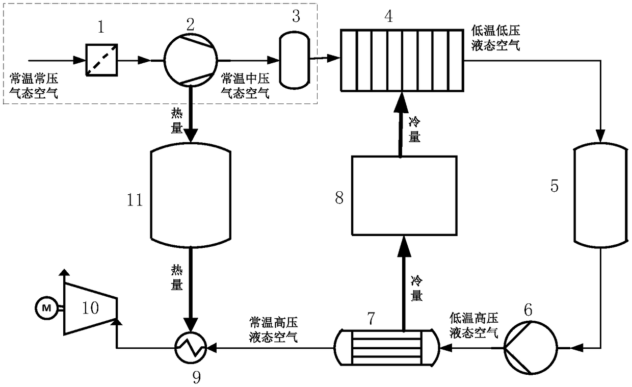
[0054] Embodiment 1 of the present invention provides a cryogenic liquefied air energy storage system, the structure of which is as follows figure 1 as shown, figure 1 M in the middle represents a generator; the cryogenic liquefied air energy storage system provided in Embodiment 1 of the present invention specifically includes a compression device, a liquefaction storage device, a pressurization device 6, a gasification device 7, a cold storage device 8 and an expansion power generation device; the compression device, The liquefaction storage device, the pressurization device 6, the gasification device 7 and the expansion power generation device are connected in sequence, and the gasification device 7 is connected to the liquefaction device 4 through the cold storage device 8;

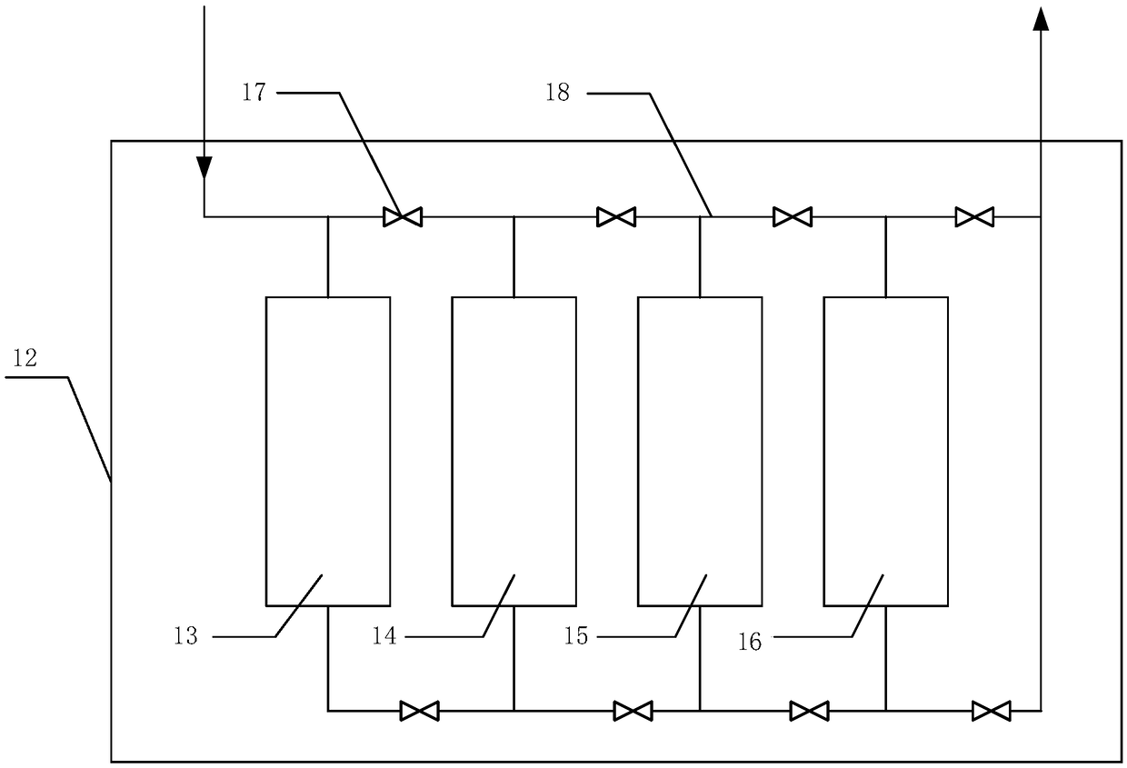
[0055] The above-mentioned cold storage device 8 includes a thermal insulation shell 12 and a plurality of cold storage tanks located inside the thermal insulation shell; multiple cold storage tanks a...

Embodiment 2

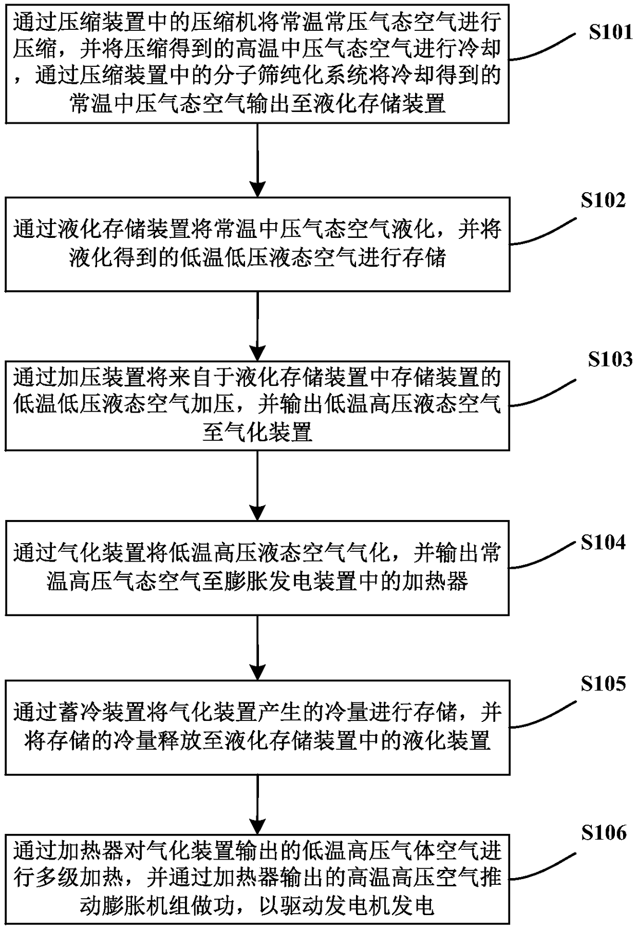
[0078] Embodiment 2 of the present invention provides a method for cryogenic liquefied air energy storage using the cryogenic liquefied air energy storage system of Embodiment 1. The flow chart is as follows image 3 As shown, the specific process is as follows:

[0079] S101: Compress the normal temperature and pressure gaseous air through the compressor 2 in the compression device, and cool the compressed high temperature and medium pressure gaseous air, and use the molecular sieve purification system 3 in the compression device to cool the normal temperature and medium pressure gaseous air output to the liquefaction storage device;

[0080] S102: Liquefy the normal-temperature and medium-pressure gaseous air through the liquefaction storage device, and store the liquefied low-temperature and low-pressure liquid air;

[0081] S103: pressurize the low-temperature and low-pressure liquid air from the storage device 5 in the liquefaction storage device through the pressurizing...


PUM


Abstract

The invention provides a cryogenic liquefied air energy storage system and method. The cryogenic liquefied air energy storage system comprises a compression device, a liquefying and storage device, apressurizing device, a gasifying device, a cold storage device and an expanding and power generation device; the compression device, the liquefying and storage device, the pressurizing device, the gasifying device and the expanding and power generation device are connected sequentially; the gasifying device is connected with the liquefying and storage device through the cold storage device; and the cold storage device comprises a heat insulation shell and multiple cold storage tanks, the multiple cold storage tanks are located inside the heat insulation shell, the cold storage device adopts the compact structure, the cold storage tanks are filled with cold storage media, thus the cold storage efficiency is increased, and the occupied area is small. According to the system and the method, only one heat insulation shell is arranged, so that the contact area of the cold storage device with the outside is greatly reduced, heat exchange of the cold storage device with the outside is reduced, the energy loss is reduced, and the storage time of high-quality cold energy is prolonged. The cold storage device of the system is high in storage capacity, high in cold storage quality, easy to manufacture and mount and relatively low in relative investment, so that the economy of the system can be improved.

Description

technical field [0001] The invention relates to the technical field of energy storage, in particular to a cryogenic liquefied air energy storage system and method. Background technique [0002] Cryogenic liquefied air energy storage technology refers to the use of electric energy for compressed air during the low load period of the grid, and the high-pressure sealing of the air in abandoned mines, subsidence subsea gas storage tanks, caves, expired oil and gas wells or newly built gas storage wells. The energy storage method releases compressed air during the peak period to drive the expander to generate electricity. The liquid air energy storage system has the advantages of large energy storage capacity, long energy storage period, small footprint and does not depend on geographical conditions. During energy storage, the electric energy compresses, cools and liquefies the air, and at the same time stores the heat energy released during the process, which is used to heat the...

Claims


Application Information

Patent Timeline
IPC IPC(8): F17C7/04F17C13/00F01B23/10B01D53/04B01D46/00
CPCB01D46/00B01D53/04F01B23/10F17C7/04F17C13/001
Inventor 梁立晓王乐徐桂芝宋洁冯涛
Owner GLOBAL ENERGY INTERCONNECTION RES INST CO LTD
Why Eureka
Try Eureka